Stator stack thickness detector

A detection device and stator technology, applied in the direction of mechanical thickness measurement, etc., can solve the problems of inaccuracy, low efficiency, slow speed, etc., and achieve the effect of accurate detection results and high efficiency

Inactive Publication Date: 2008-06-04
王伟修
View PDF0 Cites 6 Cited by
  • Summary
  • Abstract
  • Description
  • Claims
  • Application Information

AI Technical Summary

Problems solved by technology

[0002] At present, vernier calipers are basically used to measure the thickness of the stator core stack. The disadvantages are that the speed is slow, the test results are easily affected by personal factors, inaccurate and low in efficiency.

Method used


Image

  • Stator stack thickness detector

Examples


Embodiment Construction

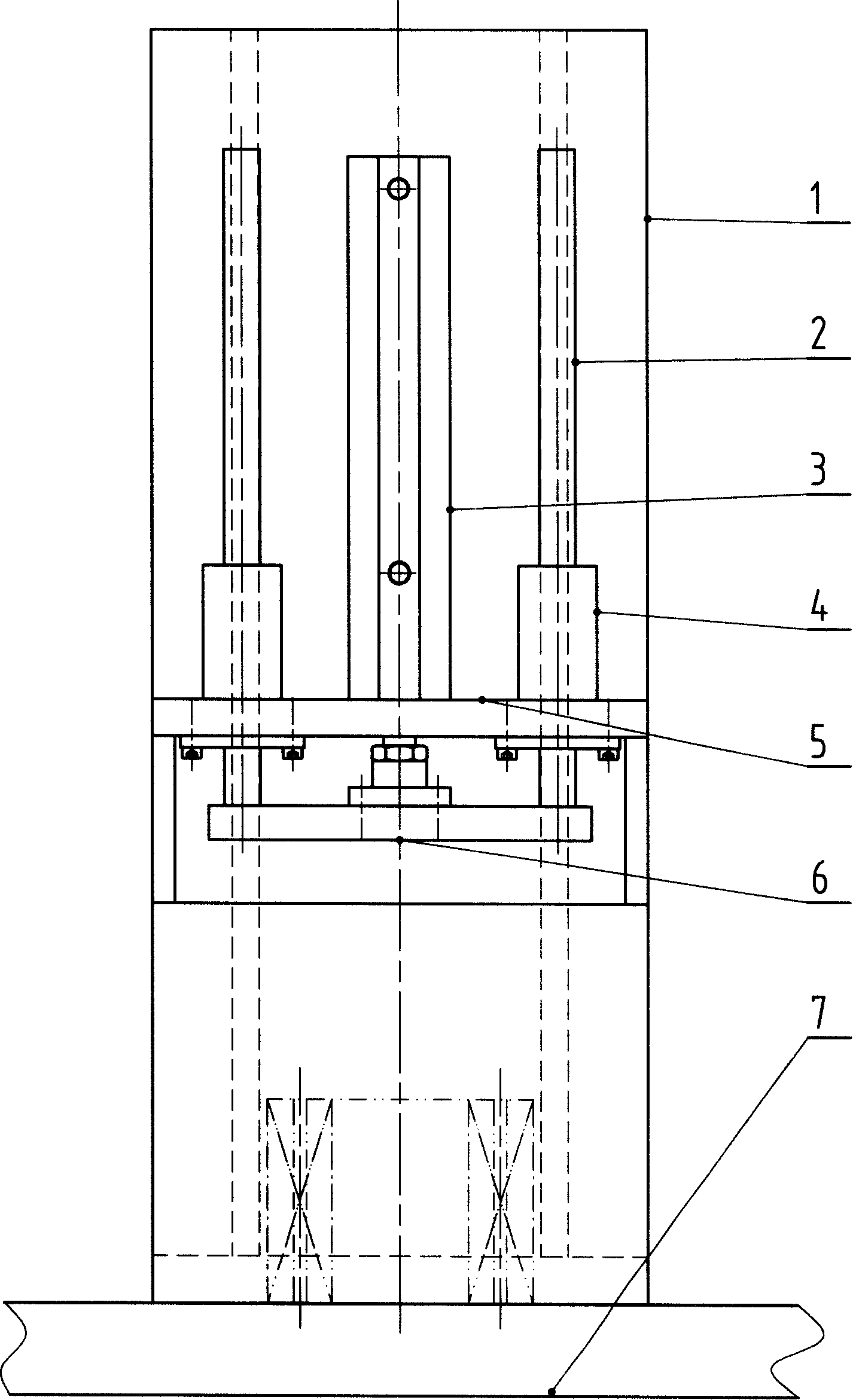
[0008] With reference to the accompanying drawings, a stator stack thickness detection device is provided with a base 1 on the panel 7, a support base 5 on one side of the base 1, a detection pressure plate 6 under the support base 5, and a stroke set on the upper end surface of the support base 5 The piston rod of the sensing cylinder 3 is fixedly connected, and a guide rod 2 is provided on the detection pressure plate 6, and the guide rod 2 is located in the guide sleeve 4 on the upper end surface of the support base 5. When in use, the stator stack thickness detection device is installed on the stator detection and marking slot assembly machine through the panel, and the operating stroke of the control system can be read out. The cylinder is guided by the guide rod to drive the detection pressure plate down to the stator core installation base surface, and measure Find a value and set this value as the reference value. Under the action of the control system, the stroke can be r...


PUM


Abstract

The invention belongs to electrician machining equipment, particularly relating to a stator thickness detection device which is used to measure the thickness of the stator iron core for the stator detection mintmark slot combined machine. The invention is characterized in that a faceplate is provided with a base of which one side is provided with a support base, a detection press plate which is arranged below the support base is fixedly connected with a piston rod of a cylinder with readable range which is arranged on the upper end face of the support base; the detection press plate is provided with a guide rod arranged in a guide sleeve on the upper end face of the support base. The invention has the advantages of accurate detection result and high efficiency.

Description

Technical field: [0001] The invention belongs to electrical machinery processing equipment, and particularly relates to a stator stack thickness detection device used for measuring the stack thickness of a stator iron core on a stator detection and marking slot combination machine. Background technique: [0002] At present, vernier calipers are basically used to measure the stack thickness of stator cores. The disadvantage is that the speed is slow, the detection results are easily affected by personal factors, and the measurement results are inaccurate and low in efficiency. Summary of the invention: [0003] The purpose of the present invention is to provide a stator stack thickness detection device with accurate detection results and high efficiency. [0004] The technical scheme of the present invention is: a base is provided on the panel, a support seat is provided on one side of the base, a detection pressure plate is provided under the support seat, and the piston rod of ...

Claims


Application Information

Patent Timeline
Patent Type & Authority Applications(China)
IPC IPC(8): G01B5/06
Inventor 王伟修赵波刘学松
Owner 王伟修
Why Eureka
Try Eureka