
Motor

A motor, hollow technology, applied in the motor field

Active Publication Date: 2008-06-04
TECO ELECTRIC AND MACHINERY
View PDF0 Cites 5 Cited by
  • Summary
  • Abstract
  • Description
  • Claims
  • Application Information

AI Technical Summary

Problems solved by technology

[0005] The purpose of the present invention is to address the above-mentioned important issues and provide a motor to solve the problems faced by the prior art, so that the stator can be wound with a simple winding method and fewer wires, and at the same time it can save winding time and The purpose of the wire

Method used


Image

  • Motor
  • Motor
  • Motor

Examples


Embodiment Construction

[0017] The implementation of the present invention is described below through specific examples, so that those skilled in the technical field of the present invention can easily understand other advantages and effects of the present invention from the content disclosed in this specification.

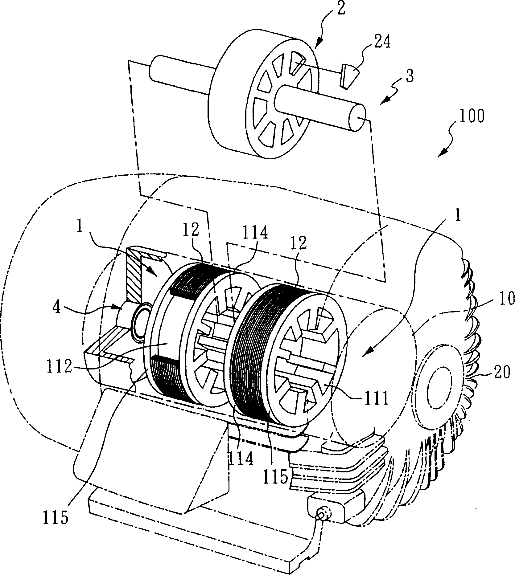
[0018] First, please also refer to image 3 , FIG. 4A, and FIG. 4B. image 3 It is a perspective view of the motor of the present invention, FIG. 4A is a cross-sectional view of the interior of the motor of the present invention, and FIG. 4B is a cross-sectional view of the stator and rotor of the motor of the present invention. It can be seen from the above three figures that the motor 100 of the present invention includes a casing 20 , two stators 1 , a rotating shaft 3 , two bearings 4 , and a rotor 2 .

[0019] The casing 20 includes an inner peripheral wall 10 , and two stators 1 , a rotor 2 , a rotating shaft 3 , and two bearings 4 and other related components are arranged therein. ...


PUM


Abstract

The invention relates to a motor, in particular to a two-stator convolved in a radial winding way. The two-stator is staggered from a special angle of the motor and forms a specific structure through coaxial arrangement with rotors, so that stator loops can be convolved with relatively a small amount of materials and a simple winding way, and the purpose of saving winding time and material is achieved.

Description

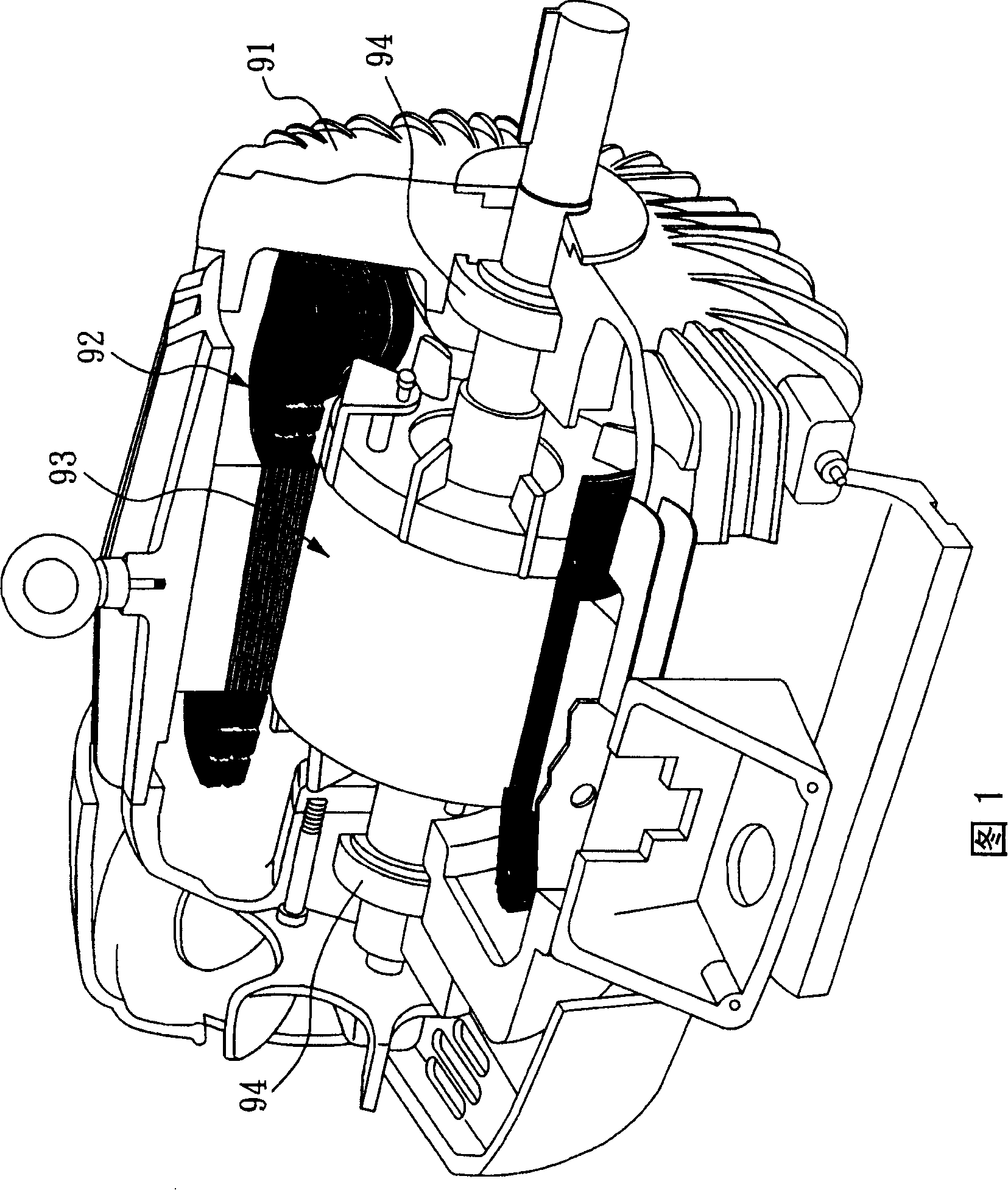
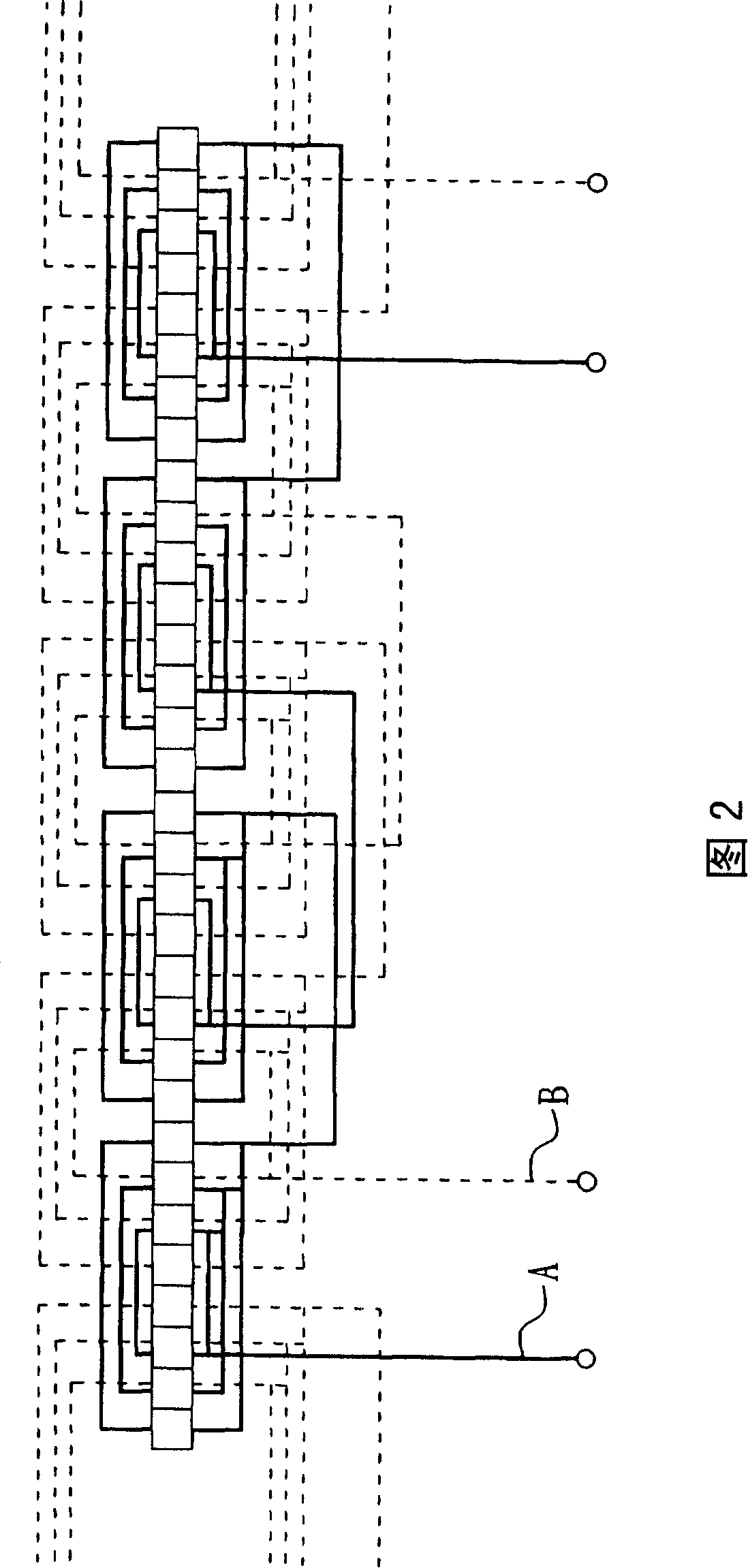
technical field [0001] The invention relates to a motor, especially a motor with a stator wound in a radial winding manner. Background technique [0002] A general conventional motor as shown in FIG. 1 includes a casing 91, a stator 92, a rotor 93, and two bearings 94. Usually, the stator 92 and the rotor 93 are formed by stacking silicon steel sheets. It is known that the inner edge of the stator 92 will be provided with several slots, and plastic slot insulators will be inserted in the slots, and then the copper wires will be inserted through the stator 92 by manual insertion according to the winding diagram shown in Figure 2. Embedding slot, then embedding plastics to make the slot wedge and cooperating with other ways to deal with after the coil is finalized, and be installed in the shell 91. [0003] However, in the known winding operation, the coils must be coiled first before entering the coils according to the interlaced and complex winding diagrams, and because the...

Claims


Application Information

Patent Timeline
Patent Type & Authority Applications(China)
IPC IPC(8): H02K1/14H02K3/18H02K1/22H02K5/16
Inventor 康基宏黄振龙陈永辉林志孝何叔彬
Owner TECO ELECTRIC AND MACHINERY
Learn More