A magnetizing fixture for multi-pole magnetization on the outer surface of a ring magnet

A multi-pole magnetization and magnetic fixture technology, which is applied to magnetic objects, electrical components, circuits, etc., can solve the problems of low magnetizing field energy, broken wires and leakage, poor magnetization consistency, etc., and achieves good cooling effect and magnetization. High consistency and uniform wiring effect

A multi-pole magnetization and magnetic fixture technology, which is applied to magnetic objects, electrical components, circuits, etc., can solve the problems of low magnetizing field energy, broken wires and leakage, poor magnetization consistency, etc., and achieves good cooling effect and magnetization. High consistency and uniform wiring effect

CN105405571BActive Publication Date: 2017-09-05NINGBO YUNSHENG BONDED MAGNET CO LTD +1

Image

  • A magnetizing fixture for multi-pole magnetization on the outer surface of a ring magnet
  • A magnetizing fixture for multi-pole magnetization on the outer surface of a ring magnet
  • A magnetizing fixture for multi-pole magnetization on the outer surface of a ring magnet

Examples


Embodiment 1

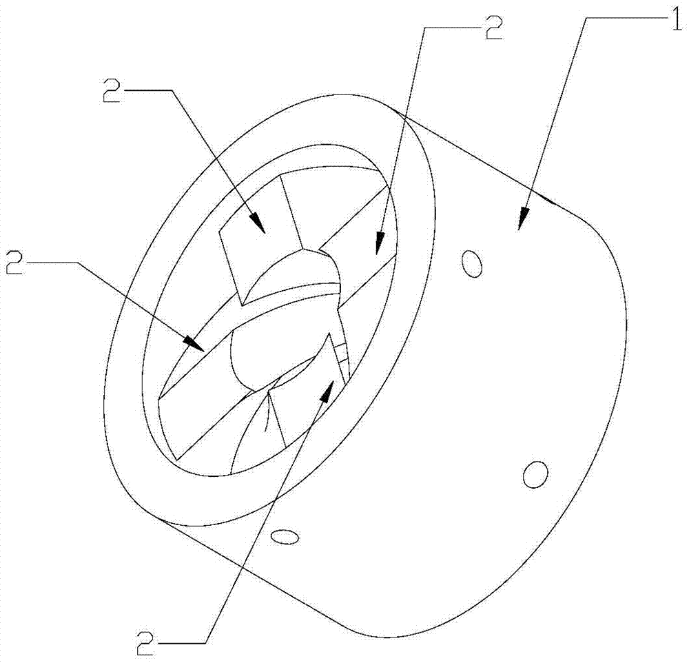
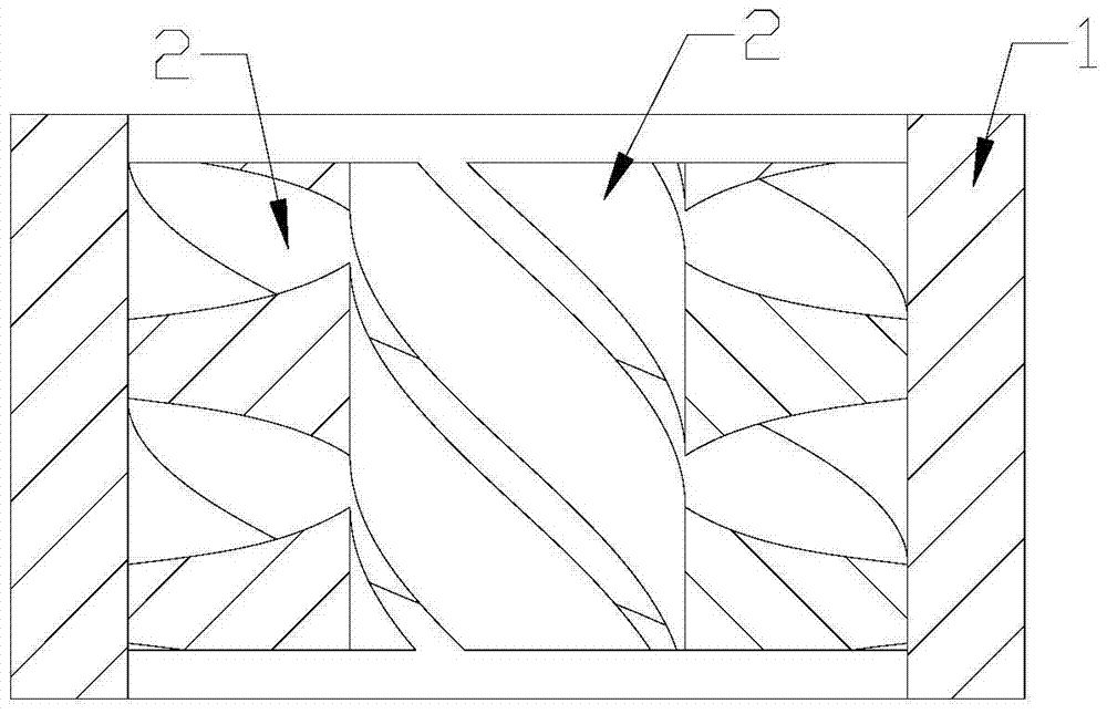
[0029] Embodiment one: if figure 1 , figure 2 , Figure 4 , Figure 5(a) ~ Figure 5(e) As shown, a magnetizing fixture for multi-pole magnetization of the outer circular surface of a ring magnet, including a circular tube-shaped substrate 1 with openings at both upper and lower ends and 2n magnetization coils, where n is an integer greater than or equal to 1;

[0030] The magnetizing coil includes a helical magnetizing pole head 2 and a multi-turn wire 3 wound on the helical magnetizing pole head 2; the shape of the helical magnetizing pole head 2 is a helical shape formed by stretching a horizontal reference plane 4 along a cylindrical helical line , the horizontal datum plane 4 is an axisymmetric closed figure composed of two parallel line segments and two concentric arcs connected; the two parallel line segments are denoted as A and B respectively, and the two concentric arcs are respectively denoted as C and D, record the distance between line segment A and line segmen...

Embodiment 2

[0033] Embodiment two: if figure 1 , figure 2 , Figure 4 , Figure 5(a) ~ Figure 5(e) As shown, a magnetizing fixture for multi-pole magnetization of the outer circular surface of a ring magnet, including a circular tube-shaped substrate 1 with openings at both upper and lower ends and 2n magnetization coils, where n is an integer greater than or equal to 1;

[0034] The magnetizing coil includes a helical magnetizing pole head 2 and a multi-turn wire 3 wound on the helical magnetizing pole head 2; the shape of the helical magnetizing pole head 2 is a spiral shape formed by stretching a horizontal reference plane 4 along a cylindrical helix , the horizontal datum plane 4 is an axisymmetric closed figure composed of two parallel line segments and two concentric arcs connected; the two parallel line segments are denoted as A and B respectively, and the two concentric arcs are respectively denoted as C and D, record the distance between line segment A and line segment B as d...

Embodiment 3

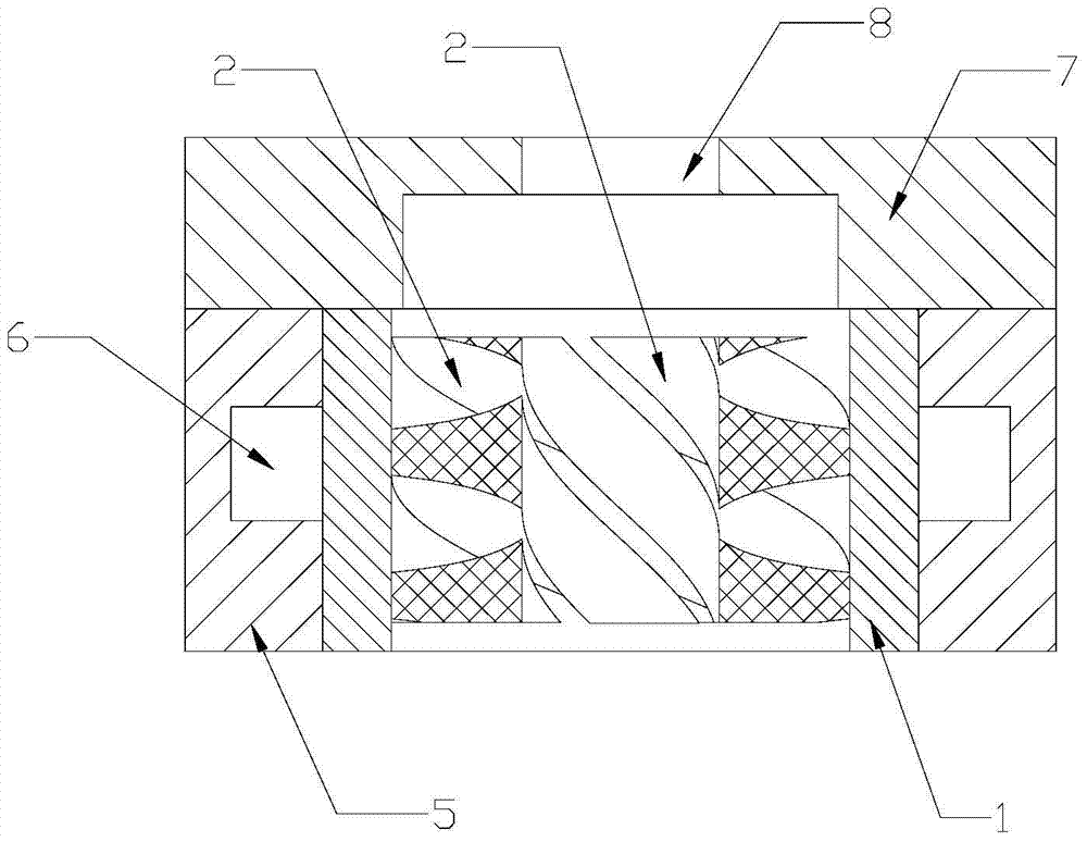
[0037] Embodiment three: as image 3 , Figure 4 , Figure 5(a) ~ Figure 5(e) As shown, a magnetizing fixture for multi-pole magnetization of the outer circular surface of a ring magnet, including a circular tube-shaped substrate 1 with openings at both upper and lower ends and 2n magnetization coils, where n is an integer greater than or equal to 1;

[0038] The magnetizing coil includes a helical magnetizing pole head 2 and a multi-turn wire 3 wound on the helical magnetizing pole head 2; the shape of the helical magnetizing pole head 2 is a helical shape formed by stretching a horizontal reference plane 4 along a cylindrical helical line , the horizontal datum plane 4 is an axisymmetric closed figure composed of two parallel line segments and two concentric arcs connected; the two parallel line segments are denoted as A and B respectively, and the two concentric arcs are respectively denoted as C and D, record the distance between line segment A and line segment B as d, ...


PUM


Abstract

The invention discloses a magnetizing fixture for multi-pole magnetization of the outer circumference surface of an annular magnet. The magnetizing fixture comprises a tubular substrate with an upper open end and a lower open end and 2n magnetizing coils, wherein n is an integer more than or equal to 1; each magnetizing coil includes a spiral magnetizing pole head and a multi-turn lead winding on the spiral magnetizing pole head; the spiral magnetizing pole head takes the shape of a spiral which is formed by stretching along a cylindrical spiral from a horizontal reference plane; the spiral magnetizing pole head is provided with a left curved surface, a right curved surface, an upper end face, a lower end face, an internal cylindrical surface and an external cylindrical surface; one lead is formed into the multi-turn lead by uniformly winding on a closed ring surface formed by the left curved surface, the right curved surface, the upper end face and the lower end face of the spiral magnetizing pole head. The magnetizing fixture adopts the winding manner of winding the single lead, thus being simple in winding mode, uniform in winding displacement, high in magnetizing field energy and magnetizing consistency; and furthermore, due to the single lead, the potential safety hazard of electric leakage caused by damage is inexistent, and thereby the magnetizing fixture is high in safety.

Description

technical field [0001] The invention relates to a magnetizing fixture, in particular to a magnetizing fixture for multi-pole magnetization on the outer surface of a ring magnet. Background technique [0002] The principle of the magnetizing coil is to generate an induced magnetic field by an energized solenoid. The magnetic field strength is related to the energizing current and the number of coil turns. Under the same magnetizing current strength, the more coil turns, the greater the magnetic field strength. The direction of the magnetic field is according to the right-hand rule, the four fingers point to the direction of the current, and the thumb points to the direction of the N pole of the magnetic field. At present, when the magnetic ring is magnetized with multiple poles on the outer circular surface, it is usually necessary to install the magnetic ring in the magnetizing fixture connected to the magnetizing machine, and then turn on the magnetizing machine to magneti...

Claims


Application Information

Patent Timeline
05 Sep 2017
Publication
CN105405571B
IPC
H01F13/00
Inventors
赵帅; 程波波