System for guiding a probe over the surface of the skin of a patient or an animal

A probe and patient technology, which is applied in the vascular system and the field of medical diagnosis, can solve problems such as unsatisfactory results, and achieve the effect of increasing safety and comfort, low cost, and cost saving

Inactive Publication Date: 2008-06-04
KONINKLIJKE PHILIPS ELECTRONICS NV
View PDF2 Cites 10 Cited by
  • Summary
  • Abstract
  • Description
  • Claims
  • Application Information

AI Technical Summary

Problems solved by technology

However, the results are unsatisfactory when the patient still mov

Method used


Image

  • System for guiding a probe over the surface of the skin of a patient or an animal
  • System for guiding a probe over the surface of the skin of a patient or an animal
  • System for guiding a probe over the surface of the skin of a patient or an animal

Examples


Embodiment Construction

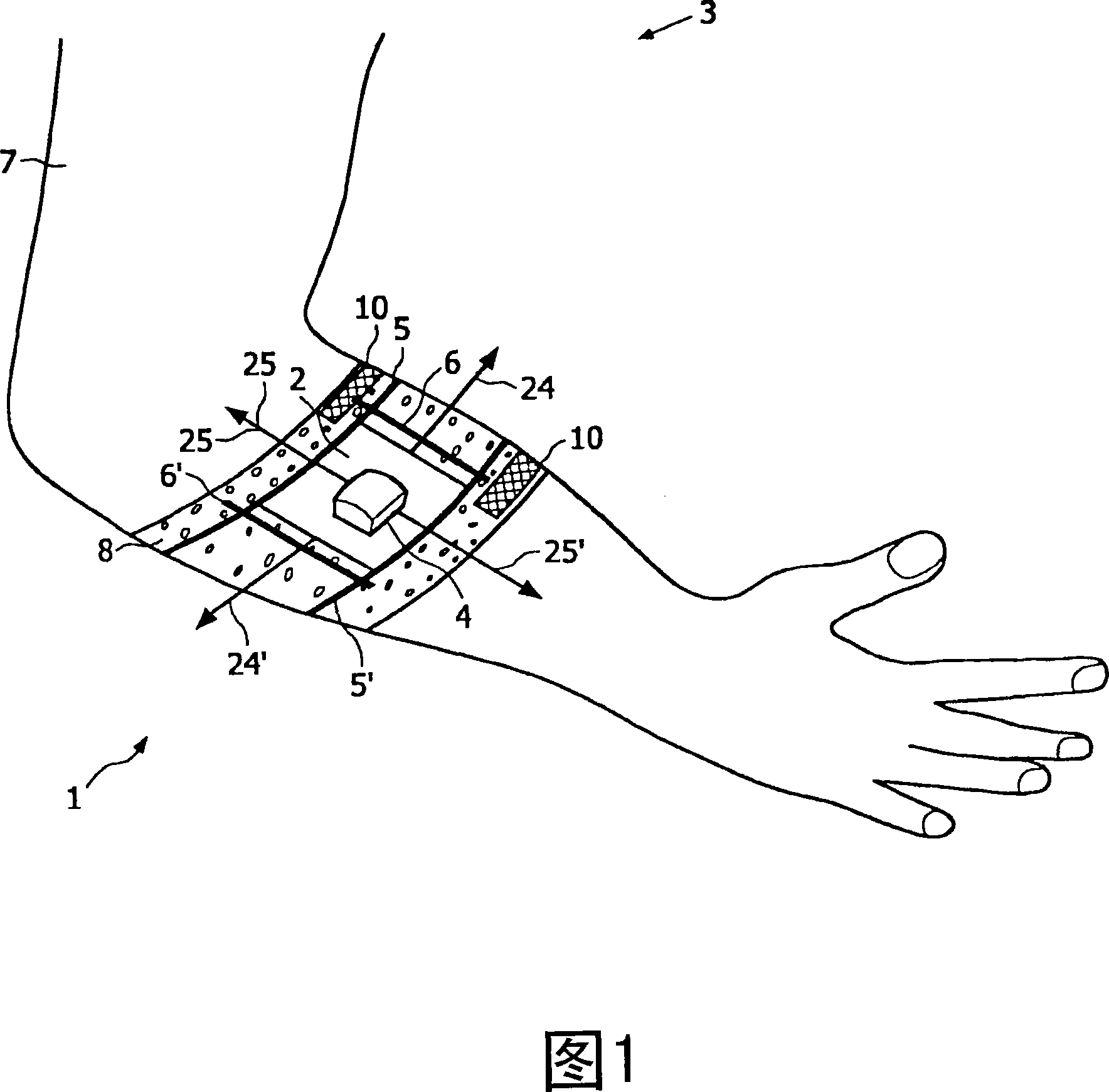
[0091] Figure 1 shows a guidance system 1 according to the invention. The system 1 is wrapped around the arm 7 of the patient 3 . It has a strap 8 of rectangular shape, 15 cm wide, and adjustable in length by means of Velcro fasteners 7 . By suitable use of the Velcro fastener 10 it is possible to ensure that the strap 8 fits snugly on the arm of the patient 3 .

[0092] Two flexible tracks 5, 5' are located on the belt 8.

[0093] The rails 5, 5' are made of polypropylene and are spaced approximately 7 cm apart in a parallel configuration. The probe holder 2 is movably mounted between the rails 5, 5' and carries the probe 4. The probe 4 is screwed on the probe holder 2 . The probe holder 2 may travel parallel to the rails 5, 5' as indicated by arrows 24 and 24'. The first rail 5, 5' is movably mounted on the second rail 6, 6', while the alignment direction of the rails 6, 6' is perpendicular to the alignment direction of the rails 5, 5'. Thus, the probe holder...


PUM


Abstract

The invention relates to a system for guiding a probe over the surface of the skin of a patient. Performing measurements with ultrasound techniques for small structures such as blood vessels need well-defined spatial relationship between the measuring probe and the tissue which has to be examined. The invention seeks to ensure a movement of the measuring probe in a controlled and precise way over the skin. Therefore, a system 1 is suggested which comprises a probe holder 2 to which a probe 4 is rigidly attachable. The probe holder 2 is moveable along at least one rail 5, 5'. The rail can be wrapped around the patient 3 or a body part 7 of the patient or the animal.

Description

technical field [0001] The present invention relates to medical diagnosis of the skin and tissues and structures below the skin, and in particular to the field of cannulation, thus the insertion of a cannula or needle into the vasculature of a human or animal. technical background [0002] For medical diagnosis of the skin or subcutaneous structures using ultrasound systems or the like, it is necessary to position the measurement probe above the skin so that the ultrasound waves can penetrate the patient's body. Ultrasound can then be used to produce two-dimensional (2D) or three-dimensional (3D) images of the scanned body part, producing images of blood vessels, kidneys or liver, for example. [0003] Especially when imaging of smaller objects such as blood vessels is to be performed, the movement of the probe relative to the scanned object becomes more critical. Such movement reduces the effective spatial resolution of the image and should therefore be avoided. However, ...

Claims


Application Information

Patent Timeline
IPC IPC(8): A61B8/00A61M5/42
CPCA61B8/4461A61B5/0059A61B5/0073A61B5/1075A61B5/489A61B8/4227A61M5/427A61B5/0095A61B5/0066A61B8/4209A61B5/06A61B8/06A61B8/0833A61B8/0841A61B2090/366
Inventor C·施瓦赫S·内尔肯G·W·吕卡森M·格里格斯F·J·M·弗里德R·赫金伯格N·L·W·艾克兰伯格
Owner KONINKLIJKE PHILIPS ELECTRONICS NV
Why Eureka
Try Eureka