A lock key and a method of its manufacture

A technology of keys and key blanks, applied in the field of lock keys

Inactive Publication Date: 2008-06-04
ASSA
View PDF0 Cites 2 Cited by
  • Summary
  • Abstract
  • Description
  • Claims
  • Application Information

AI Technical Summary

Problems solved by technology

Finally, keys must be manuf...

Method used


Image

  • A lock key and a method of its manufacture
  • A lock key and a method of its manufacture
  • A lock key and a method of its manufacture

Examples


Embodiment Construction

[0023] Preferred embodiments of the present invention are described in detail below.

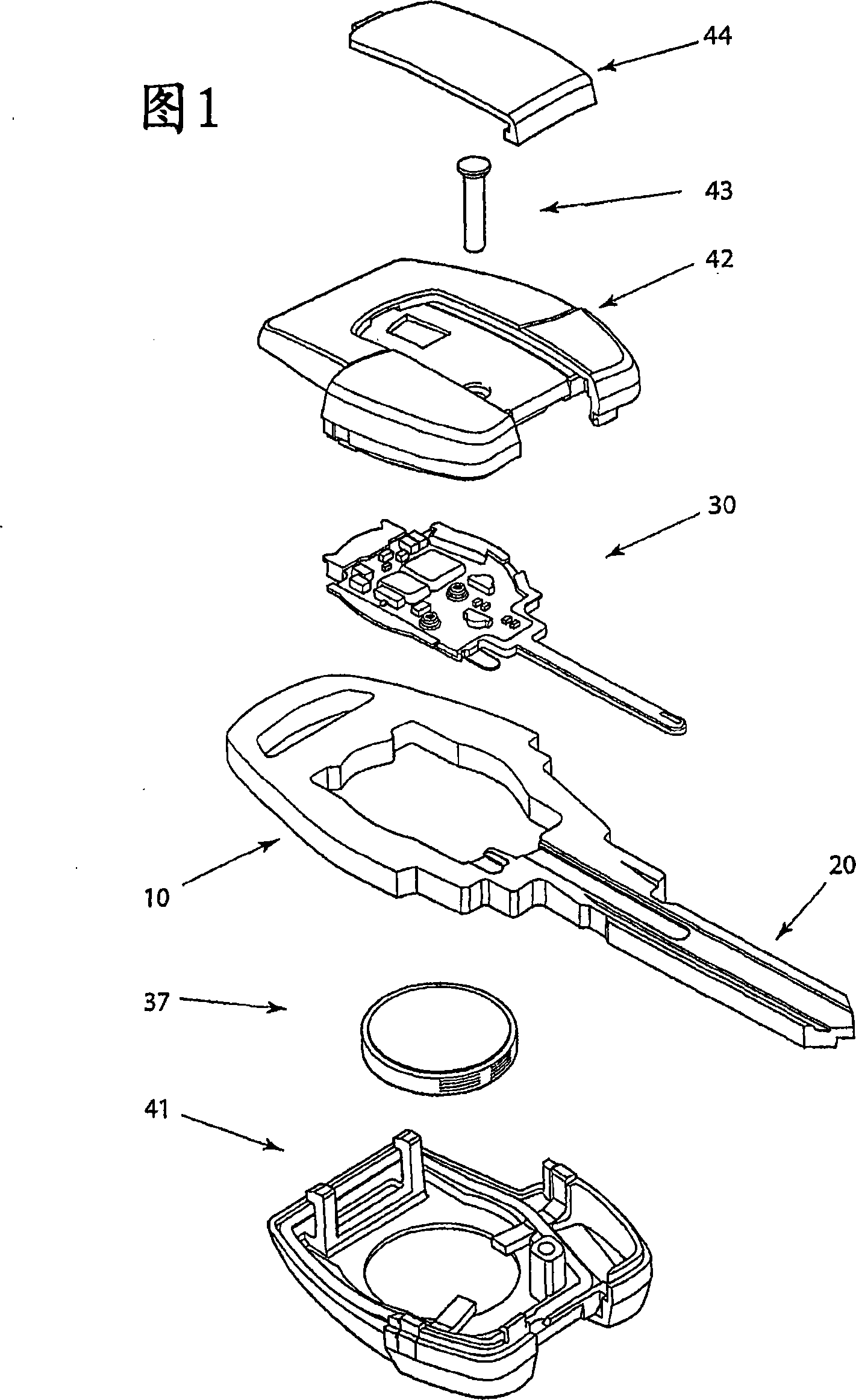
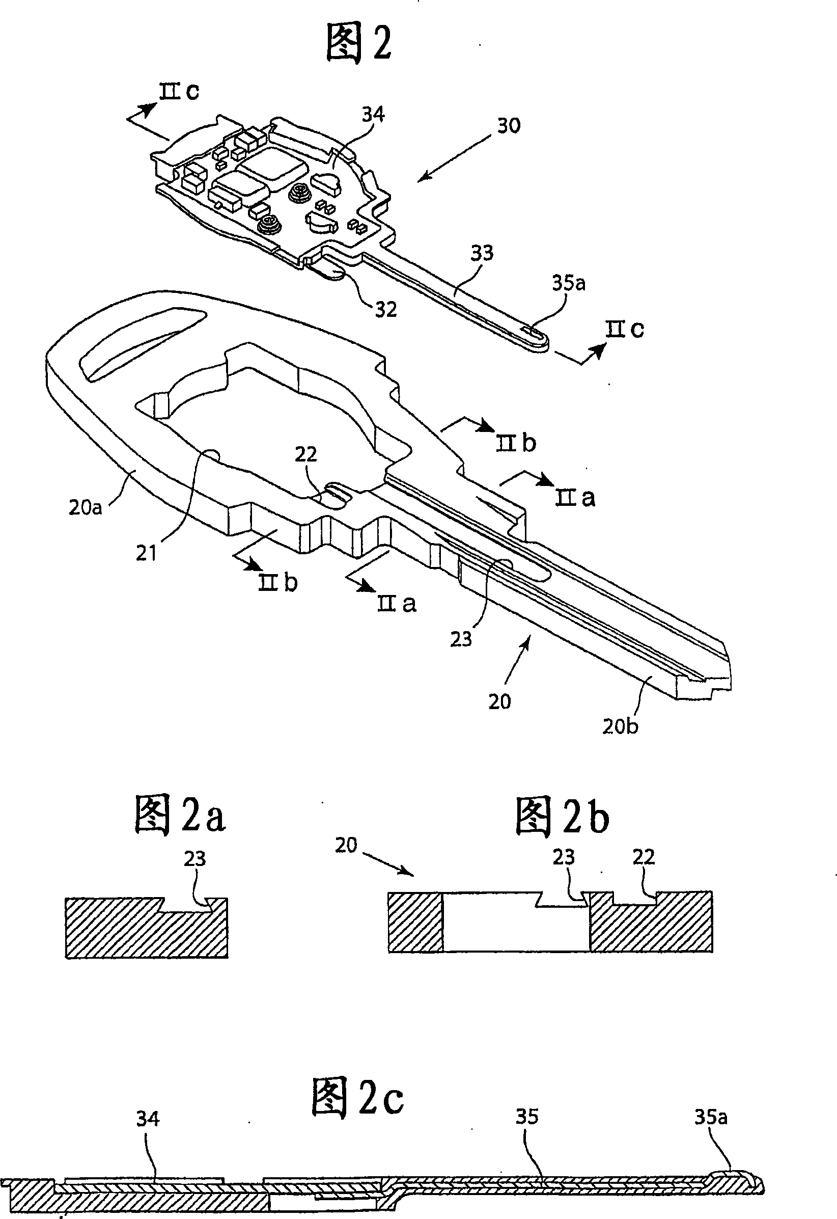
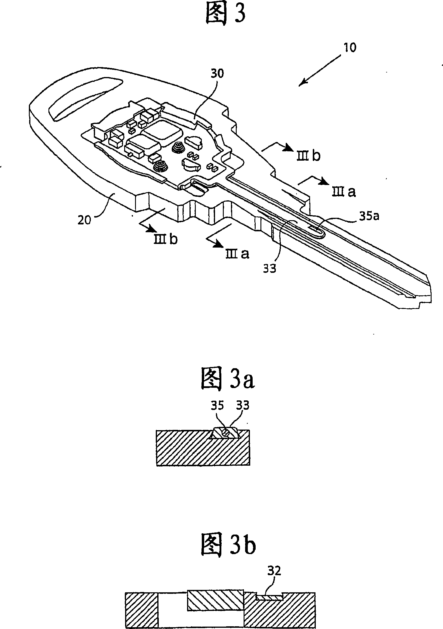
[0024] Figure 1 is an exploded view of a key according to the invention. The key, generally indicated by reference numeral 10, is intended for use in so-called electromechanical lock cylinders (lock-cylinder), the key 10 comprising: a key blank 20, which is formed from a suitable conductive metal; a circuit board support 30, which is formed from a suitable composed of non-conductive materials, such as plastic materials. The manner in which the bracket is fitted to the key blank will be described in detail in the following description with reference to FIGS. 2 and 3 .

[0025] The key 10 comprises a battery 37 for supplying electric current to the electronics provided in the key and possibly also to the electronics provided in the lock cylinder into which the key is inserted. The battery is held in place by the lower housing portion 41 which interacts with the key blank via hook elements. ...


PUM


Abstract

A lock key, comprising: a key blank (20), including a handle portion (20a) and a key head portion (20b). Housed in a circuit board holder (30) supported by a non-conductive material are: a circuit board (34) mounted with an electrical circuit; and a key contact portion (35) electrically connected to the electrical circuit. The circuit board holder is assembled to the key blank. The placement of the circuit board and the electrical contact conductors in a non-conductive material enables a rational manufacture of the device. It is thus possible to fix the circuit board carrier made of non-conductive material in the key blank, so that the electrical contact conductors can be placed precisely, thereby ensuring a reliable electrical contact function.

Description

technical field [0001] The present invention relates generally to lock keys, and more particularly to keys for electromechanical locks, the key comprising electrical contact conductors connected to an electronic device carrying the key, the electronic circuitry interacting with the electrical conductors on which the lock is mounted. The invention also relates to a method of manufacturing such a key. Background technique [0002] Such electromechanical lock devices designed to be operated by means of a key comprising key electronics are known in the prior art. These electronic devices include electronic circuits such as processors and memory circuits mounted on circuit boards. In order to be able to communicate with the corresponding electronics in the lock device, the key contact portion is provided somewhere on the key, preferably on the head of the key. Furthermore, the actual key blank is often used as a ground for the electrical circuit, so that the key electronics are...

Claims


Application Information

Patent Timeline
IPC IPC(8): G07C9/00E05B19/00
CPCE05B19/04G07C9/00944G07C2009/00761Y10T70/7254Y10T70/7791
Inventor 丹尼尔·安德森
Owner ASSA
Why Eureka
Try Eureka