Optical plate

An optical plate and transparent layer technology, applied in the field of optical plates, can solve the problems of reducing light utilization rate, light energy consumption and loss increase, etc., and achieve the effects of improving light utilization rate, reducing light transmission loss, and improving optical uniformity

Inactive Publication Date: 2008-06-11
HONG FU JIN PRECISION IND (SHENZHEN) CO LTD +1
View PDF0 Cites 7 Cited by
  • Summary
  • Abstract
  • Description
  • Claims
  • Application Information

AI Technical Summary

Problems solved by technology

[0004] However, in the prior art, the diffusion plate 13 and the prism sheet 15 are prepared separately, which makes the diffusion plate 13 and the prism sheet 15 independent of each other. During use, although the diffusion plate 13 and the prism sheet 15 can be in close contact, there is still a gap between the diffusion plate 13 and the prism sheet 15. There will be a fine air barrier layer; when the light propagates between the diffuser plate 13 and the prism sheet 15 and passes through the air barrier layer, the light will easily occur at the interface between the air barrier layer and the diffuser plate 13 and the prism sheet 15. Interface reflection and other effects increase the consumption and loss of light energy, thereby reducing the utilization rate of light

Method used


Image

  • Optical plate
  • Optical plate
  • Optical plate

Examples


Embodiment Construction

[0017] The optical plate will be further described in detail with reference to the accompanying drawings and embodiments.

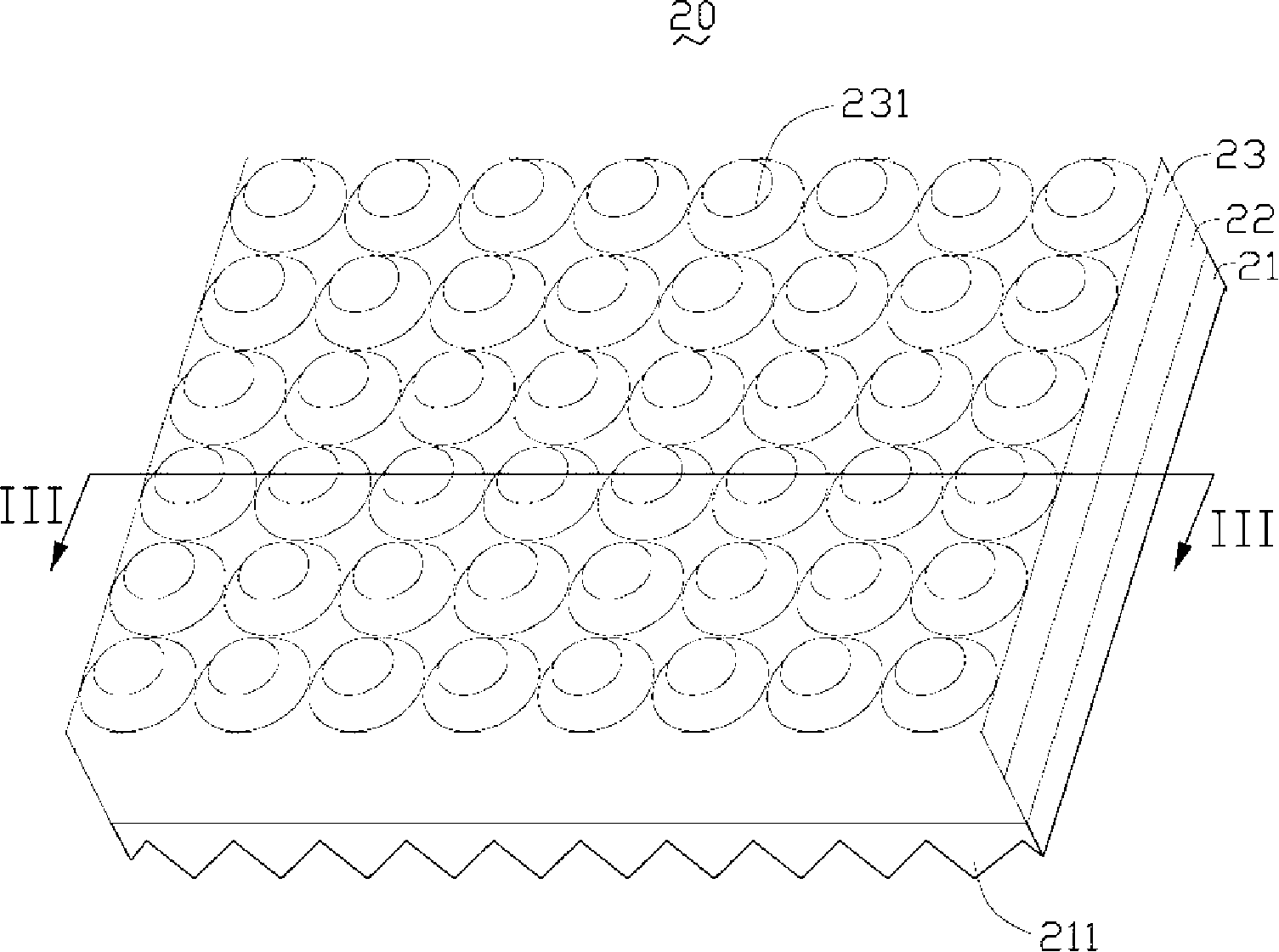
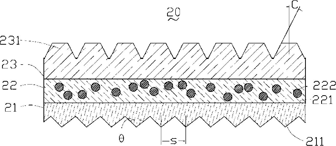
[0018] see figure 2 , the optical plate 20 of the preferred embodiment 1 of the present invention includes an integrally formed first transparent layer 21, a diffusion layer 22 and a second transparent layer 23, that is, the first transparent layer 21 is formed by injection molding through a mold, and then formed on the first transparent layer. The diffusion layer 22 is formed by injection molding on the diffusion layer 21, and then the second transparent layer 23 is formed by injection molding on the diffusion layer 22. It can be understood that the formation sequence of the first transparent layer 21, the diffusion layer 22, and the second transparent layer 23 can also be used as Appropriate changes, but the diffusion layer 22 of the formed optical plate 20 needs to be located between the first transparent layer 21 and the second transparent layer 23 ....


PUM

PropertyMeasurementUnit
thicknessaaaaaaaaaa
angleaaaaaaaaaa

Abstract

The invention discloses an optical plate which comprises a first diaphanotheca, a diffusion layer and a second diaphanotheca all-in-one. The diffusion layer is between the first diaphanotheca and the second diaphanotheca, which comprises translucent resin and diffusion particles diffused in the translucent resin. On the surface of the first diaphanotheca opposite to the diffusion layer are a plurality of V-shaped prisms and on the surface of the second diaphanotheca opposite to the diffusion layer are a plurality of heaves in cone shape. The optical plate is characterized in that the optical plate can elevate the utilization rate of the ray.

Description

technical field [0001] The invention relates to an optical plate used in a backlight module, in particular to a composite optical plate. Background technique [0002] Liquid crystal display devices are widely used in electronic products such as personal digital assistants, notebook computers, digital cameras, mobile phones, and LCD TVs. However, since the liquid crystal panel of the liquid crystal display device itself does not have luminous characteristics, in order to achieve a good display effect, it is necessary to provide the liquid crystal panel with a light source device, such as a backlight module, whose function is to supply the liquid crystal panel with a surface with sufficient brightness and uniform distribution. light source. [0003] See figure 1 , a schematic cross-sectional view of a backlight module using an existing diffuser plate and a prism sheet. The backlight module 10 includes a reflector 11 , and a plurality of light sources 12 , a diffusion plate ...

Claims


Application Information

Patent Timeline
Patent Type & Authority Applications(China)
IPC IPC(8): G02B5/02G02B1/04G02F1/1335
CPCG02B5/0278G02F1/133606G02B5/0215G02B5/0242G02F2001/133607G02F1/133607
Inventor 许东明章绍汉
Owner HONG FU JIN PRECISION IND (SHENZHEN) CO LTD
Why Eureka
Try Eureka