

Optical plate
A technology of optical plates and transparent layers, which is applied in the field of optical plates, can solve the problems of increased light energy consumption and loss, and reduced light utilization, and achieve the effects of reduced light transmission loss, improved light utilization, and reduced interface loss
- Summary
- Abstract
- Description
- Claims
- Application Information
AI Technical Summary
Problems solved by technology
Method used
Image

Examples
Embodiment Construction
[0015] The optical plate will be further described in detail with reference to the accompanying drawings and embodiments.
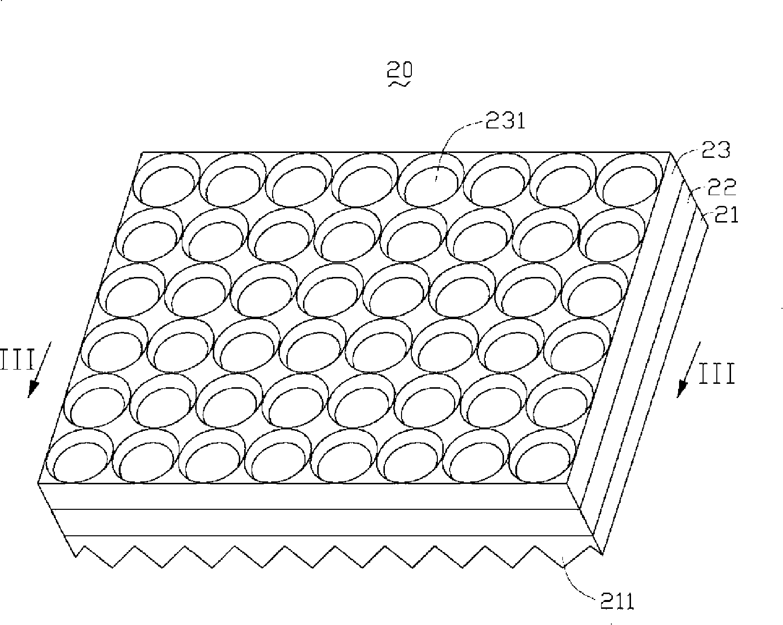
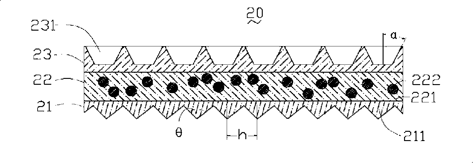
[0016] See figure 2 , the optical plate 20 includes a first transparent layer 21 , a diffusion layer 22 and a second transparent layer 23 integrally formed. The diffusion layer 22 is located between the first transparent layer 21 and the second transparent layer 23 . The outer surface of the first transparent layer 21 opposite to the diffusion layer 22 has a plurality of V-shaped protrusions 211 , and the outer surface of the second transparent layer 23 opposite to the diffusion layer 22 has a plurality of conical grooves 231 . Please also see image 3 , the diffusion layer 22 includes a transparent resin 221 and diffusion particles 222 dispersed in the transparent resin 221 . In addition, the integrally formed first transparent layer 21, diffusion layer 22 and second transparent layer 23 can be achieved by injection molding; the thicknesses of the di...
PUM
| Property | Measurement | Unit |
|---|---|---|
| Thickness | aaaaa | aaaaa |
| Top angle | aaaaa | aaaaa |
| Center distance | aaaaa | aaaaa |
Abstract
Description
Claims
Application Information