Method for preparing glass optical fiber prefabricated stick

A glass optical fiber, preform technology, applied in glass manufacturing equipment, manufacturing tools, etc., can solve the problems of high production cost, large interface loss, short production time, etc., to avoid secondary wire drawing process, reduce interface loss, improve contact performance effect

Inactive Publication Date: 2007-02-14
SOUTH CHINA UNIV OF TECH
View PDF2 Cites 0 Cited by
  • Summary
  • Abstract
  • Description
  • Claims
  • Application Information

AI Technical Summary

Problems solved by technology

The invention solves the problems of large interface loss, large processing amount, long production time, high production cost and inaccurate control existing in the existing optical fiber preform manufacturing method, can precisely control the structure of the optical fiber, has small interface loss and short production time , the advantages of high production efficiency

Method used


Image

  • Method for preparing glass optical fiber prefabricated stick
  • Method for preparing glass optical fiber prefabricated stick

Examples


Embodiment 1

[0013] A method for preparing an optical fiber preform, comprising the following steps:

[0014] (1) The cladding glass is melted by a conventional method, and the hollow tubular optical fiber cladding body is obtained by precision machining after annealing;

[0015] (2) Preheating the hollow tubular optical fiber cladding body at 400°C for 2 hours;

[0016] (3) After the core glass is melted, it is poured into the preheated hollow tubular optical fiber cladding body and annealed to obtain a glass optical fiber preform.

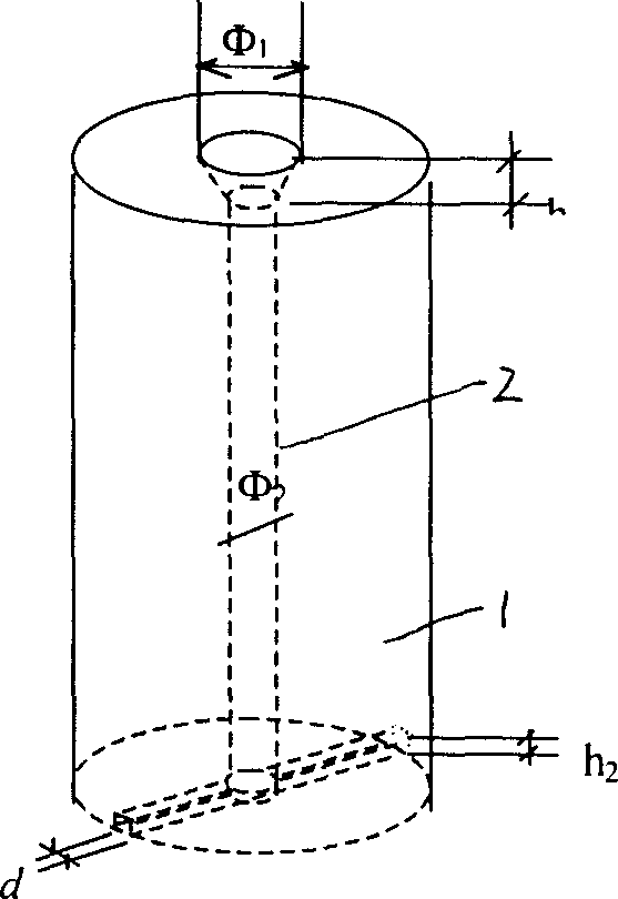
[0017] The hollow tube of the above-mentioned hollow tubular optical fiber cladding body is a top diameter Φ 1 = 8mm, height h 1 = 4mm tapered sprue, the bottom end of the hollow tube is width d = 2mm, height h 2 = 2mm exhaust channel, the middle of the cladding body is diameter Φ 2 = 5 mm hollow tube.

[0018] figure 2 It is the end view of the tellurite optical fiber drawn by the new process of this embodiment. It can be seen that the cladding and th...

Embodiment 2

[0020] A method for preparing an optical fiber preform comprises the following steps: interface loss is the key to reducing optical fiber loss. Moreover, the processing amount of the preform prepared by the tube and rod method is relatively large, which is time-consuming and material-intensive, and the requirements for the mechanical processing performance of the glass are also relatively high. It is difficult to use the tube and rod method to prepare the preform for some brittle and low-hardness glasses. Therefore, it is necessary to find a suitable processing technology to improve the processing efficiency of the preform and improve the effect of the preform processing.


PUM

PropertyMeasurementUnit
transition temperatureaaaaaaaaaa
softening pointaaaaaaaaaa
diameteraaaaaaaaaa

Abstract

The preparation process of prefabricated glass fiber stick includes the following steps: smelting the coating glass, annealing and precise treatment to obtain tubular fiber coating body; preheating the tubular fiber coating body at temperature between the glass transformation temperature and the glass softening temperature; smelting the fiber core glass, casting into the preheated tubular fiber coating body and annealing to produce the prefabricated glass fiber stick. The new technological process has the advantages of both sucking injection process and tubular rod process, and has effectively improved fiber core and coating contact performance and lowered fiber interface loss. The present invention is especially suitable for making prefabricated glass fiber stick with fiber glass with poor mechanical performance and the corresponding drawing.

Description

technical field [0001] The invention relates to a method for preparing a glass optical fiber prefabricated rod, in particular to a method for preparing a glass optical fiber prefabricated rod by combining two processes of a tube rod method and a pouring method. Background technique [0002] The fiber optic industry emerged in the 1970s. For more than 20 years, the fiber optic manufacturing process has been continuously evolving. Since the optical fiber preform manufacturing technology is the core of the optical fiber manufacturing process, the optical fiber industry has always used the optical fiber preform manufacturing technology to name the optical fiber manufacturing process. The manufacturing methods of optical fiber preform mainly include vapor deposition method, tube rod method and suction injection method. The vapor phase deposition method is to mix various precursor gases for the preparation of the core or cladding materials at high temperature to form powders of ...

Claims


Application Information

Patent Timeline
Patent Type & Authority Patents(China)
IPC IPC(8): C03B37/012
CPCC03B37/01268
Inventor 姜中宏杨中民刘粤惠张伟南陈东丹
Owner SOUTH CHINA UNIV OF TECH
Why Eureka
Try Eureka