Multi-light tube backlight module

A technology of backlight module and lamp tube, applied in optics, nonlinear optics, instruments, etc., can solve problems such as high cost and inability to automate production

Inactive Publication Date: 2008-06-11
LIEN CHANG ELECTRONICS ENTERPRISE
View PDF0 Cites 0 Cited by
  • Summary
  • Abstract
  • Description
  • Claims
  • Application Information

AI Technical Summary

Problems solved by technology

[0007] In addition, as shown in FIG. 4, when the backlight module 2 is assembled, the control circuit board 20 and the cold cathode lamps L1-LN must be connected to the connecting wires 24 through the high-voltage-resistant conn

Method used


Image

  • Multi-light tube backlight module
  • Multi-light tube backlight module
  • Multi-light tube backlight module

Examples


Embodiment Construction

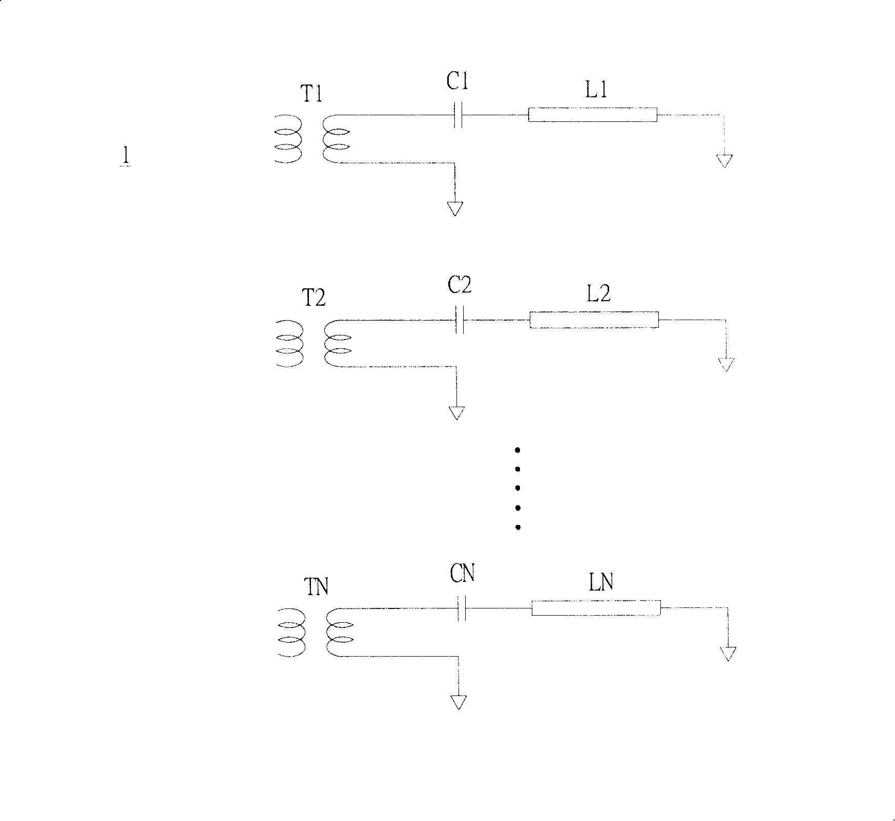
[0044] Please refer to Figure 5 , which is a schematic circuit diagram of the backlight module according to the first embodiment of the present invention. The backlight module 3 of the present invention uses a driving transformer T to provide high-voltage driving signals to the cold-cathode lamps L1-LN through the high-voltage capacitors C1-CN in a one-to-many manner, and then drives the cold-cathode lamps L1-LN. Suitable for a liquid crystal display panel (not marked).

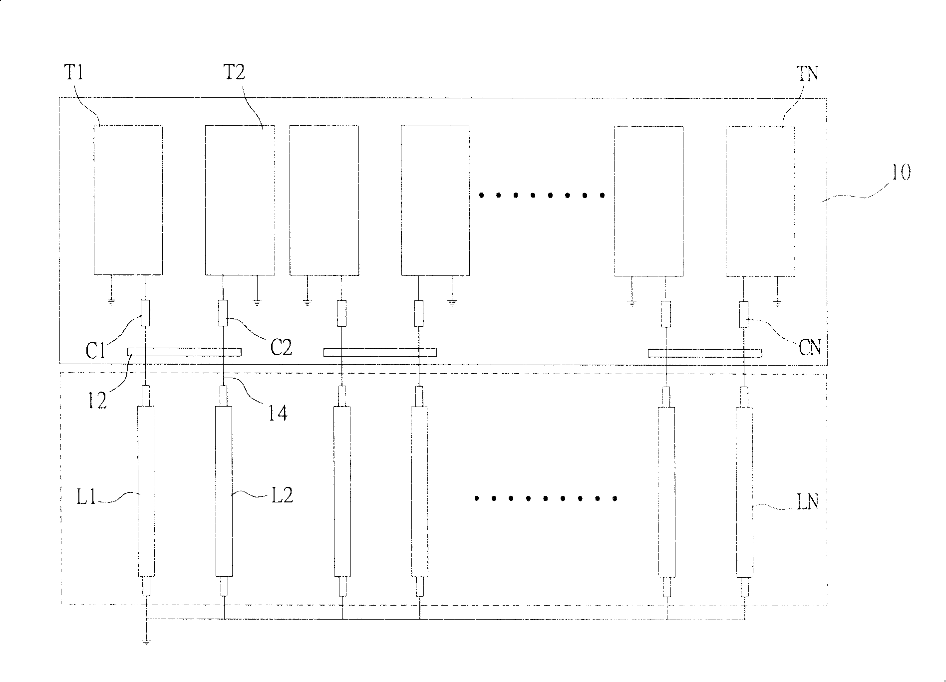
[0045] Cooperate Figure 5 ,refer to Image 6 ,it's for Figure 5 Schematic diagram of the circuit setup. exist Image 6 Among them, the backlight module 3 of the present invention includes a drive unit 30 and a backlight unit 32, the drive unit 30 includes a control circuit board 300 and a drive transformer T, and the backlight unit 32 includes a circuit board 320 and at least one cold cathode lamp L1- LN. The drive transformer T is disposed on the control circuit board 300 , and the secondary side of t...


PUM


Abstract

A backlight module with multiple lighting tubes is provided, which is to integrate the capacitor onto one circuit board mounted beside the LCD panel. The backlight module comprises a drive unit with a drive transformer which provides two output terminals; a backlight unit comprising a circuit board equipped on one side of the LCD panel with at least one capacitor. One of the ends of the capacitors is all connected with an output terminal of the drive transformer; and at least one CCFL (cold cathode florescent lamp) arranged at the back of the LCD panel. One of the ends of another output terminal of the drive transformer and the other ends of the cold cathode florescent lamps are separately connected with another ends of the capacitors.

Description

technical field [0001] The present invention is a multi-lamp backlight module, especially a multi-lamp backlight module with reduced cost and better current balance by reducing the use of electronic components and simplifying the circuit design. Background technique [0002] A general liquid crystal display device mainly includes a liquid crystal display panel and a backlight module, wherein the backlight module can be roughly divided into a direct type backlight module and an edge type backlight module. [0003] Regardless of the type of backlight module, at least one driving circuit board is required to drive the light-emitting unit in the backlight module. Currently, the most common light-emitting unit is a cold cathode lamp (CCFL), and the one used to drive the light-emitting unit is a cold-cathode lamp (CCFL). It is driven by a high-voltage driving signal provided by the driving circuit board. [0004] Referring to FIG. 1 , it is a schematic circuit diagram of a conven...

Claims


Application Information

Patent Timeline
IPC IPC(8): G02F1/1335G09G3/34
Inventor 陈振刚王政雄
Owner LIEN CHANG ELECTRONICS ENTERPRISE
Why Eureka
Try Eureka