
Steering device for a superposition steering system

A steering device and steering system technology, which is applied to the steering control, steering mechanism, electric steering mechanism and other directions installed on the car, to achieve the effect of reliable self-locking, reducing axial distance, and eliminating play

Active Publication Date: 2008-06-11
JOYSON SAFETY SYST GERMANY GMBH
View PDF1 Cites 7 Cited by
  • Summary
  • Abstract
  • Description
  • Claims
  • Application Information

AI Technical Summary

Problems solved by technology

This actuator has the disadvantage that it is arranged between the input shaft and the output shaft, with the result that additional installation space is required in the area of ​​the steering column, thus requiring a special steering column

Method used


Image

  • Steering device for a superposition steering system
  • Steering device for a superposition steering system
  • Steering device for a superposition steering system

Examples


Embodiment Construction

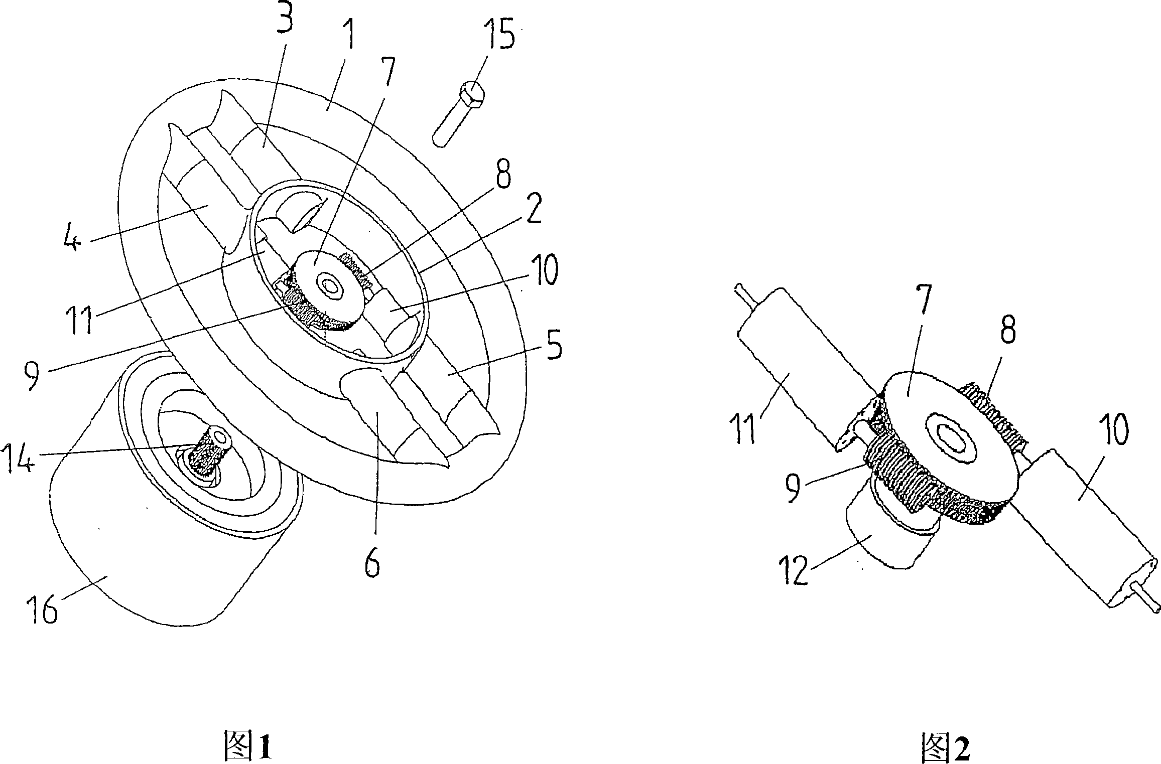
[0038] FIG. 1 shows a steering wheel with a steering wheel rim 1 and a steering wheel hollow 2 , wherein the steering wheel hollow 2 is shown in section to make the actuators visible. The steering wheel rim 1 and the steering wheel hollow 2 are connected to each other via spokes 3 , 4 , 5 , 6 . The actuator has a large worm wheel 7, two small worm wheels 8, 9 and an electric motor 10, 11 associated with the latter. The motor 10 is an integral part of the spoke 5 and the electric motor 11 is an integral part of the spoke 4 . The large worm wheel 7 has a sleeve 12 ( FIG. 2 ), by means of which the steering wheel can be fastened to a steering shaft 13 ( FIG. 3 ). The sleeve 12 engages over the steering wheel journal 14 and the two are connected to each other by screws 15 .

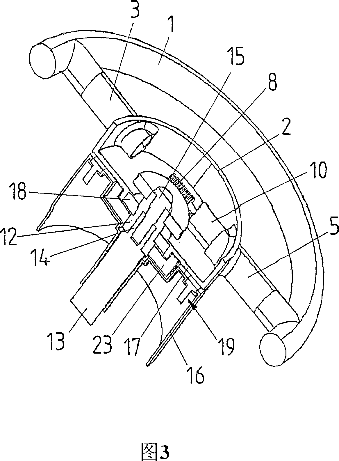
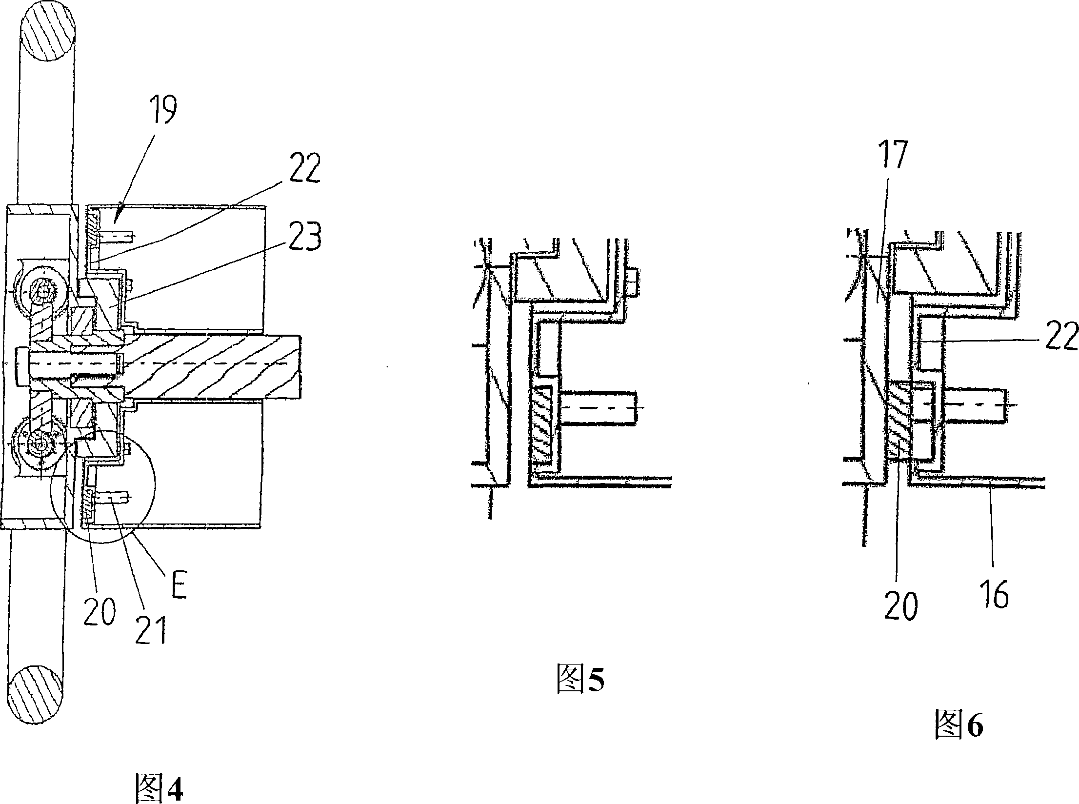
[0039] Further details of the arrangement according to the invention can be seen from FIG. 3 . The steering wheel hollow 2 has a steering wheel base 17 in which a ball bearing 18 for mounting the sleeve 12...


PUM


Abstract

The invention relates to a steering device for a superposition steering system using at least one actuator. The invention is based on the object of producing a superposition steering system which requires no additional installation space in the steering column. According to the invention, the actuator (7-11) for the superposition steering system is therefore arranged in the steering wheel (1, 2).

Description

technical field [0001] The invention relates to a steering arrangement of a superposition steering system according to the preamble of claim 1 . Background technique [0002] Motor vehicles today are often equipped with power steering systems. The purpose of the power steering system is to reduce the steering force requirement, that is, to reduce the torque applied by the driver to change the direction of travel. In existing power steering systems, this occurs as the engine speed varies since the pump of the auxiliary hydraulic system is driven by the vehicle's electric motor. In addition, it is known to drive a pump by actuating an electric motor, with the result that a speed-dependent auxiliary steering force is possible. Here, as the speed increases, the assistance effect of such a power steering system decreases. Therefore, at high speeds, the driver has to apply more torque through the steering wheel to change the steering lock than at low speeds. In such systems, t...

Claims


Application Information

Patent Timeline
Patent Type & Authority Applications(China)
IPC IPC(8): B62D5/04
CPCB62D1/10B62D5/008
Inventor 迪特尔·马克福特
Owner JOYSON SAFETY SYST GERMANY GMBH
Learn More