
Ball-and-socket joint with sensor system and wear measurement method

A sensor device, ball-and-socket joint technology, applied in bearing assembly, transportation and packaging, traction connectors, etc., can solve the problems of high manufacturing overhead, failure threat, and high cost of ball-and-socket joints, and achieve the effect of low cost

Inactive Publication Date: 2008-06-11
ZF FRIEDRICHSHAFEN AG
View PDF1 Cites 21 Cited by
  • Summary
  • Abstract
  • Description
  • Claims
  • Application Information

AI Technical Summary

Problems solved by technology

All in all, this makes the production of the ball joint with the load sensor complex and therefore very expensive, and the exposed sensor system and the wiring of the ball joint are also very sensitive and therefore subject to failure.

Method used


Image

  • Ball-and-socket joint with sensor system and wear measurement method
  • Ball-and-socket joint with sensor system and wear measurement method
  • Ball-and-socket joint with sensor system and wear measurement method

Examples


Embodiment Construction

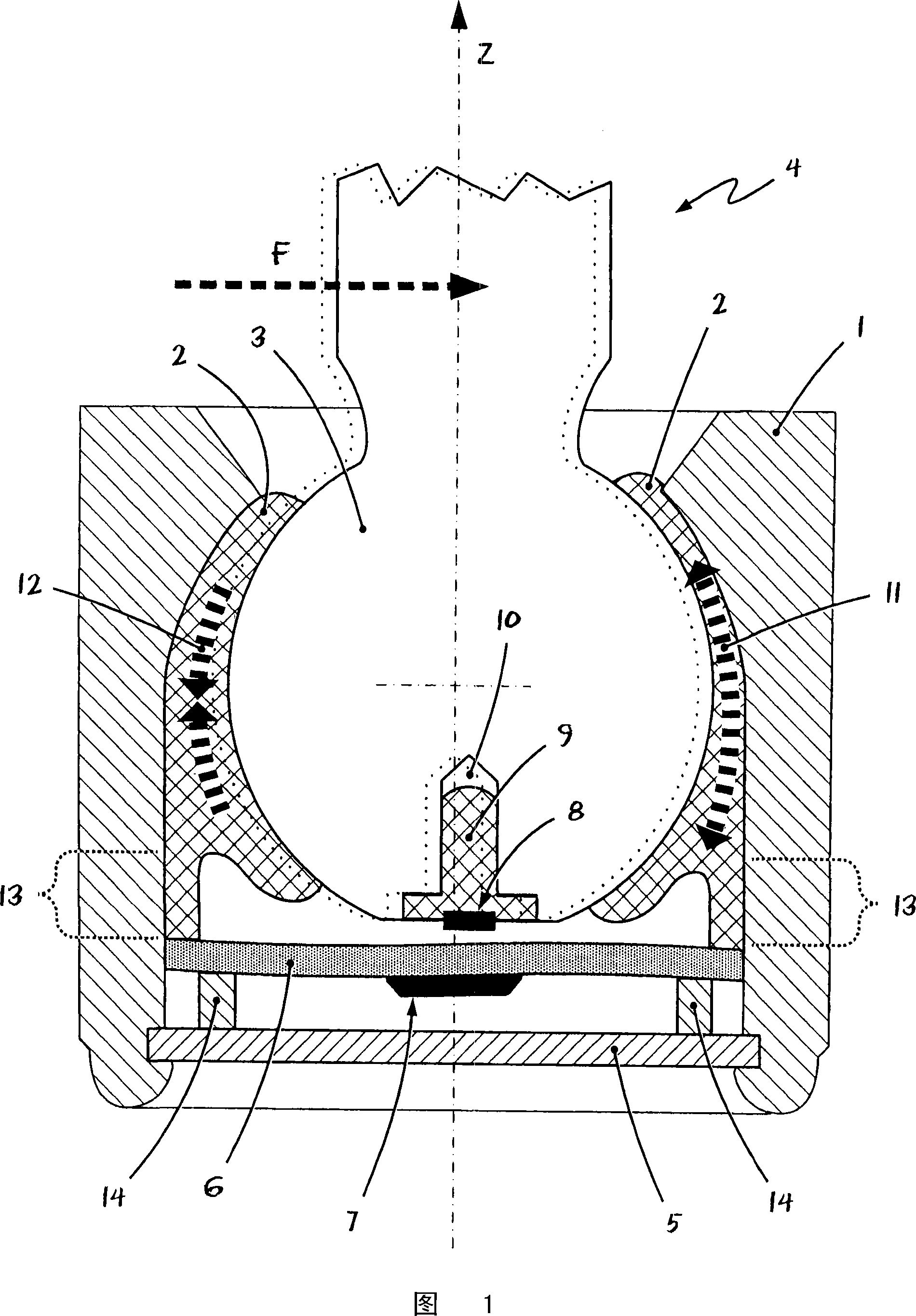
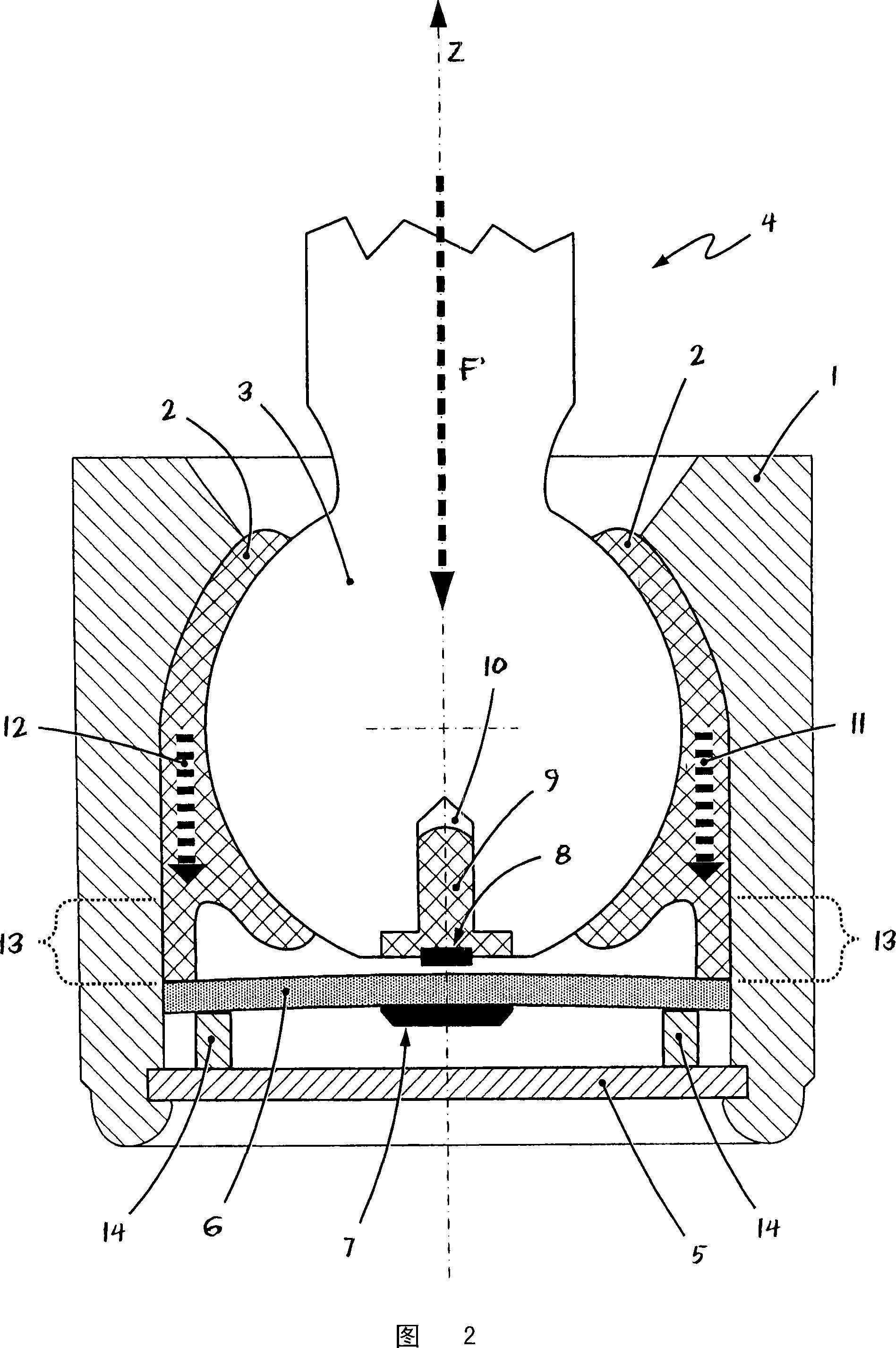
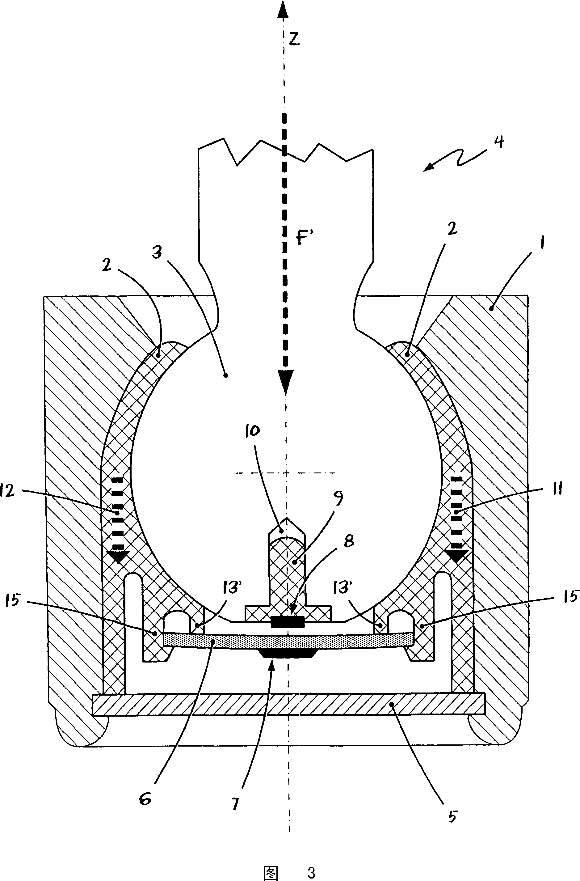
[0042] FIG. 1 shows a schematic longitudinal section through an embodiment of a ball joint according to the invention. Here, a substantially pot-shaped joint housing 1 can be seen, which has a bearing shell or spherical bush 2 arranged therein. The ball 3 of the spherical pin 4 is again arranged in the interior of the spherical bush 2 .

[0043] Furthermore, the ball joint according to FIG. 1 has a sensor printed circuit board 6 arranged between the joint ball 3 and the housing cover 5 . A sensor device 7 , shown only schematically, is arranged on the sensor printed circuit board 6 . The sensor device 7 is located in the vicinity of a magnetic field emitter 8 designed as a permanent magnet, which is arranged in a bore 10 of the joint ball 3 by means of a plastic plug 9 .

[0044] In this case, the sensor device 7 is designed in such a way that it can detect the magnetic field of the permanent magnet 8 in all three directions in space, in other words, it can detect the magnet...


PUM


Abstract

The invention relates to a ball joint, eg for an axle system of a motor vehicle, and to a method for measuring wear on a ball joint. The ball and socket joint has an essentially annular or pot-shaped joint housing (1), in the essentially cylindrical interior of which a spherical bushing (2) is arranged. The ball (3) of the spherical journal (4) is slidably accommodated in the spherical bushing (2). Furthermore, the ball and socket joint has a sensor device ( 7 ) for force or load measurement. According to the invention, the ball and socket joint is distinguished in that the sensor device ( 7 ) is arranged on a flexurally elastic printed circuit board ( 6 ). The printed circuit board (6) is flexibly and movably fixed in the joint housing (1), wherein the sensor device (7) is configured to adjust the curvature or Mechanical stress is measured. In this case, the ball and socket joint includes a transmission element by means of which a force or a bending moment is introduced into the sensor printed circuit board (6) when the spherical bushing (2) deforms. The ball joint according to the invention can be produced very robustly and inexpensively and allows the measurement of forces or loads acting on the ball joint. The method according to the invention permits permanent determination of the state of wear of the ball joint by means of the measurement of the prestressing force of the spherical bushing.

Description

technical field [0001] The invention relates to a ball and socket joint according to the preamble of claim 1 with a sensor device, in particular for an axle system or wheel suspension of a motor vehicle. Furthermore, the invention relates to a method for measuring wear on a ball and socket joint according to claim 15 . Background technique [0002] Ball and socket joints of the type mentioned at the outset are used, for example, but not exclusively—for example as support joints or as guide joints—in the chassis of motor vehicles or in wheel suspensions. In this case, a ball joint of the type described includes a sensor device with which forces and loads acting on the ball joint can be determined or measured. [0003] Ball and socket joints of the type mentioned at the outset with a device for measuring forces or loads are used, for example, in motor vehicles in order to be able to reliably determine the effect there during real vehicle operation or also during test runs on ...

Claims


Application Information

Patent Timeline
Patent Type & Authority Applications(China)
IPC IPC(8): F16C11/06
CPCB60D1/305F16C11/0647B60D1/30B60D1/58F16C11/0604F16C11/0633F16C11/0642F16C17/246F16C41/00F16C2233/00F16C2326/05Y10T403/32196Y10T403/32631Y10T403/32713Y10T403/32721F16C11/00F16C11/06
Inventor M·埃索伊J·斯普拉特M·克兰克P·霍夫曼
Owner ZF FRIEDRICHSHAFEN AG
Learn More