
Hydraulic pressure reducible slideway equipment capable of hiding roller

A roller and hydraulic technology, applied to furniture parts, household utensils, drawers, etc., can solve problems such as unsmooth movement of objects, large sliding friction, and large friction coefficient

Inactive Publication Date: 2008-06-18
WANTONG IND
View PDF0 Cites 4 Cited by
  • Summary
  • Abstract
  • Description
  • Claims
  • Application Information

AI Technical Summary

Problems solved by technology

The early slide rail device mainly includes two slide bars respectively arranged on the table and the drawer, wherein the slide bar arranged on the drawer will slide along the slide bar fixed on the table. To overcome the sliding friction between the sliders, if the joint surface between the sliders is not smooth enough, the friction coefficient is large, so the friction is large, causing the object to move unsmoothly, and due to the large sliding friction, it will cause the slider to wear Faster, resulting in shortened product life
In response to the above situation, people have improved the design, such as setting a roller device between the slide bars. This method of replacing sliding friction with rolling friction makes the opening and closing of the drawer much more convenient and smooth, but the stability of its structure is still not enough. Very good, but the bearing capacity is poor, and this early slide rail is not equipped with a reset device, the slide rail can slide freely in both directions along the track, when a certain pulling force is applied from the outside world or under the action of gravity on an inclined plane, the drawer will stretch out from the table. In this way, the drawer is in a very unstable state, and any small external changes will cause it to slide, so that the user must repeatedly close it, or need to use a key to fix it relative to the table body, these bring some troubles to users

Method used


Image

  • Hydraulic pressure reducible slideway equipment capable of hiding roller
  • Hydraulic pressure reducible slideway equipment capable of hiding roller
  • Hydraulic pressure reducible slideway equipment capable of hiding roller

Examples


Embodiment Construction

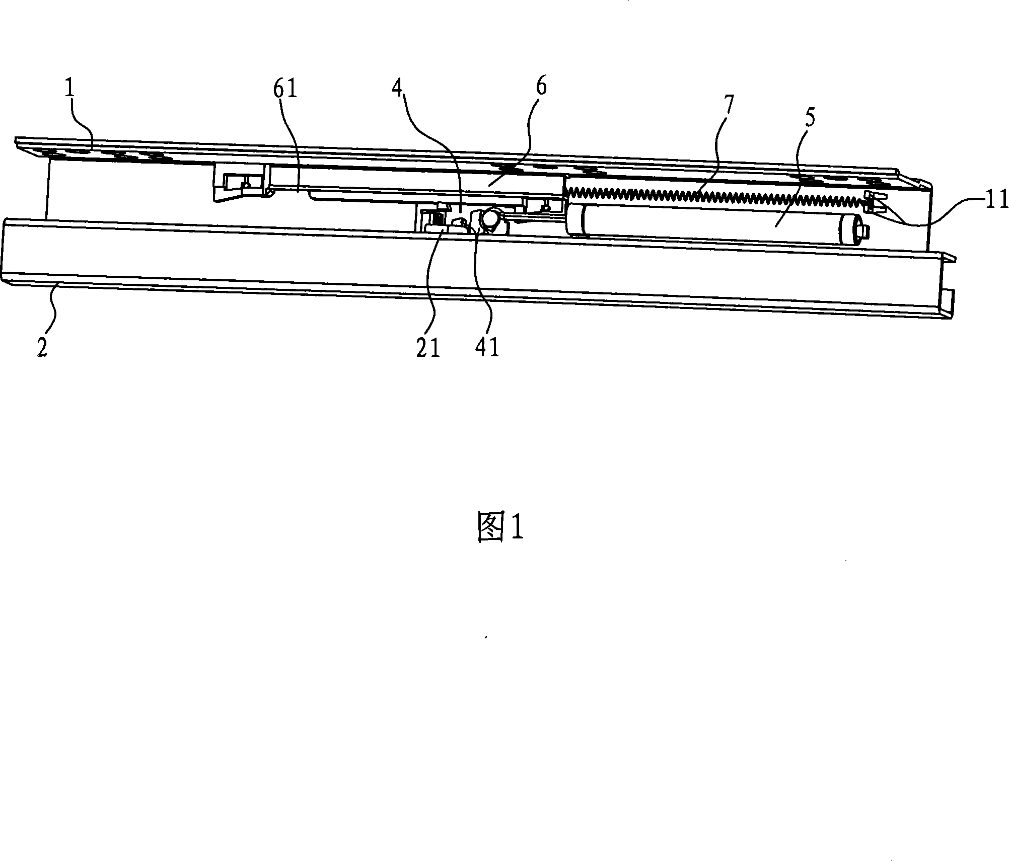
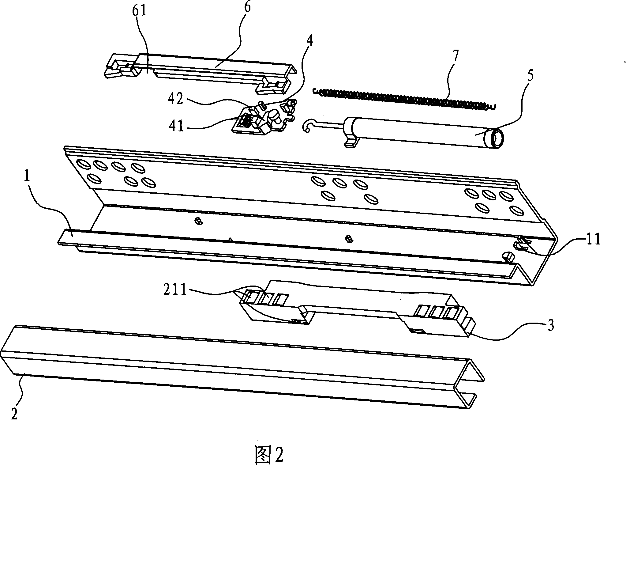
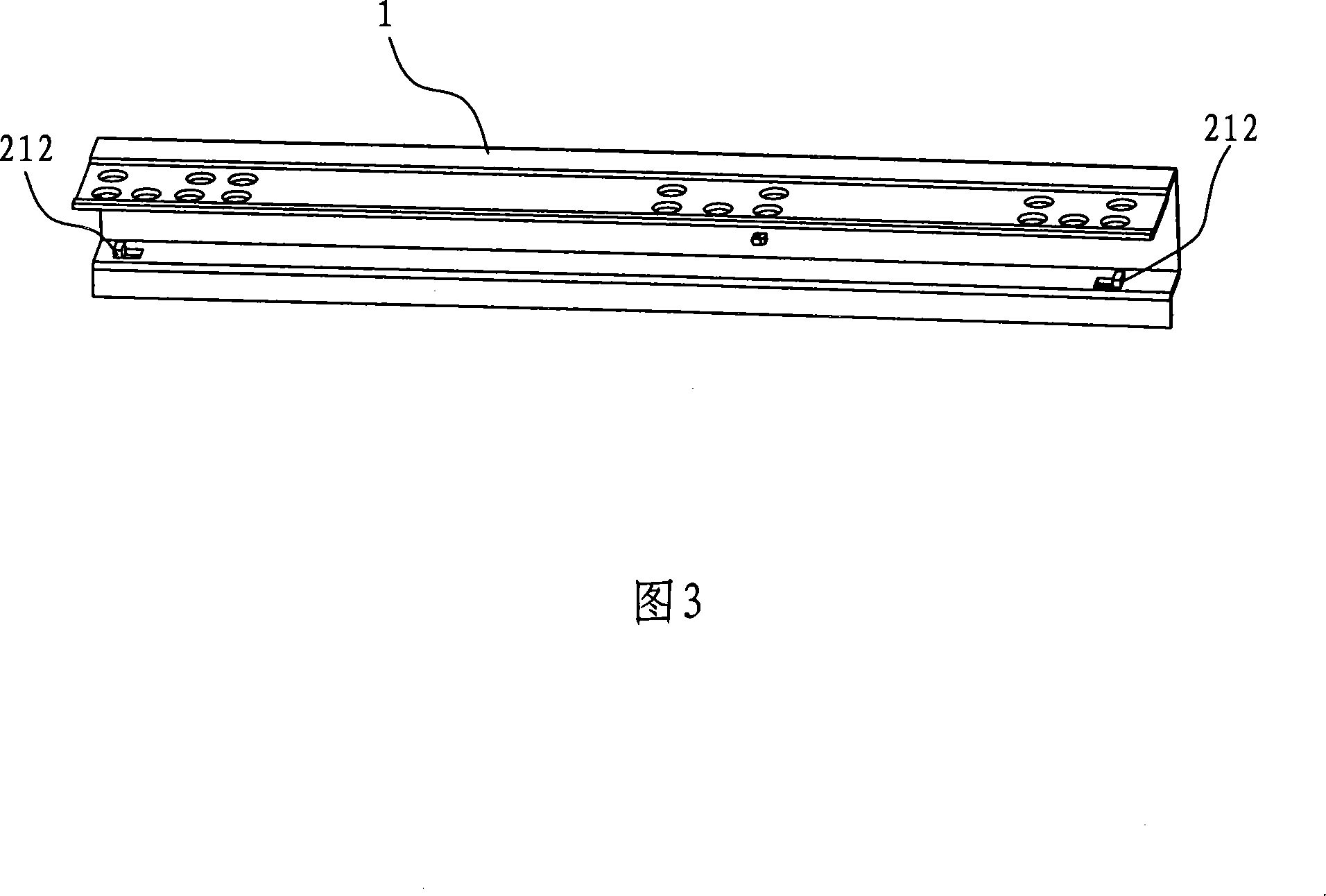
[0015] As shown in Figures 1 to 4, the present invention includes an outer rail 1 and an inner rail 2, one side of the outer rail 1 and the inner rail 2 are nested and connected by a roller bracket 3, and a reset slider 4, a hydraulic damping piston 5. Fixed cover 6 and tension spring 7; one side of the reset slider 4 is slidably set in the gap formed by the inner rail 2 and the outer rail 1, and the other side is slidably set in the fixed cover 6; the inner One end of the side of the rail 2 is provided with a dial 21 to toggle the reset slider 4, and the reset slider 4 is provided with two bumps 41 for clamping the dial 21, and one end of the reset slider 4 is provided with a reset block 42, The corresponding end of the fixed cover plate 6 is provided with a reset gap 61; one end of the tension spring 7 is affixed to the reset slider 4, and the other end is fixed in the clip 11 on the inner groove surface of the outer rail 1; the reset slider 4 rests on one end of the tension ...


PUM


Abstract

The invention relates to the technical field of dump rails, in particular to a dump rail which is characterized in that the dump rail has a concealed roller and the hydraulic pressure can reset. The invention comprises an outer rail and an inner rail; one side of the outer rail is tabled with the inner rail through a roller bracket. The invention also includes a reset slide block, a hydraulic damp piston, a fixed cover board and a tension spring. The fixed cover board is fixed at the inner groove face of the outer rail; one side of the reset slide block is slidingly arranged in the clearance of the first and the second rails and the other side is slidingly arranged inside the fixed cover board; a poke column which can poke the reset slide block is arranged at one end of the inner face of the inner rail; two projection blocks to clamp the poke column are arranged on the reset slide block, one end of the slide block is provided with a reset block plate and a reset gap is arranged at one corresponding end of the fixed cover board; one end of the tension spring is fixedly connected with the reset slide block and the other end is fixed in a clamping piece arranged on the inner groove face of the outer rail. The invention has the advantages of smooth extension and contraction, balanced movement, long service life and low noise.

Description

Technical field: [0001] The invention relates to the technical field of slide rail devices, in particular to a hydraulic resettable slide rail device with hidden rollers. Background technique: [0002] Slide rails are designed to realize the relative movement of two adjacent objects. For example, in desks used by people, the opening and closing of drawers is mostly realized through this slide rail device. The early slide rail device mainly includes two slide bars respectively arranged on the table and the drawer, wherein the slide bar arranged on the drawer will slide along the slide bar fixed on the table. To overcome the sliding friction between the sliders, if the joint surface between the sliders is not smooth enough, the friction coefficient is large, so the friction is large, causing the object to move unsmoothly, and due to the large sliding friction, it will cause the slider to wear Faster, resulting in shortened product life. In response to the above situation, pe...

Claims


Application Information

Patent Timeline
Patent Type & Authority Applications(China)
IPC IPC(8): A47B88/04A47B88/10A47B88/493
Inventor 王苏仔
Owner WANTONG IND
Learn More