Disc brakes

A disc brake, disc technology, applied in the direction of brake type, brake components, mechanical equipment, etc., can solve the problem of complex structure of anti-vibration spring

Inactive Publication Date: 2008-06-18
ADVICS CO LTD
View PDF2 Cites 11 Cited by
  • Summary
  • Abstract
  • Description
  • Claims
  • Application Information

AI Technical Summary

Problems solved by technology

[0006] However, the anti-chatter spring has a complicated structure, which has integral first biasing means and second biasing means, and is constituted by combining a plurality of straight parts and a plurality of curved parts

Method used


Image

  • Disc brakes
  • Disc brakes
  • Disc brakes

Examples


Embodiment Construction

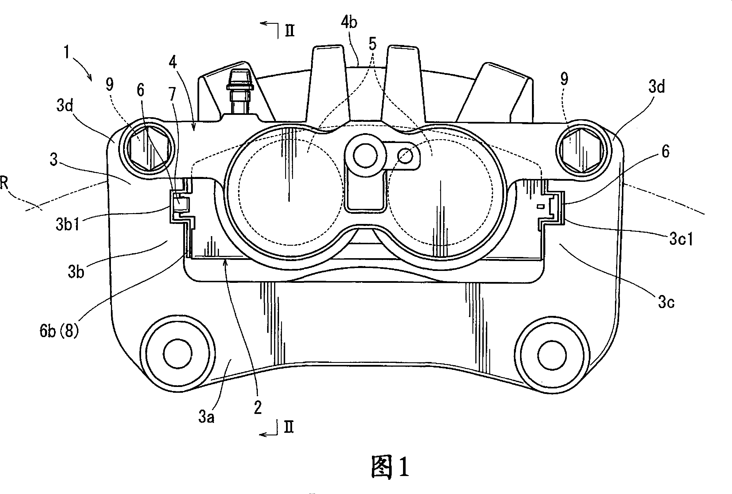
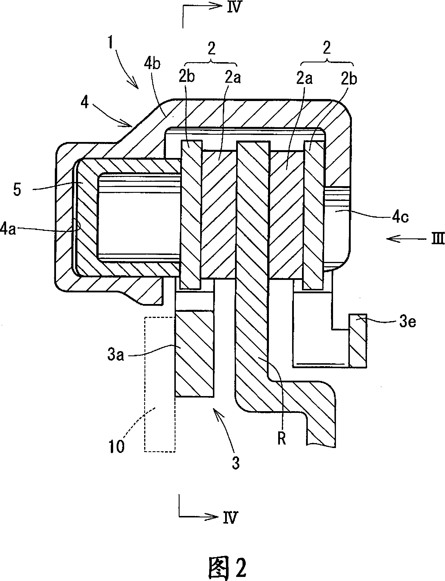
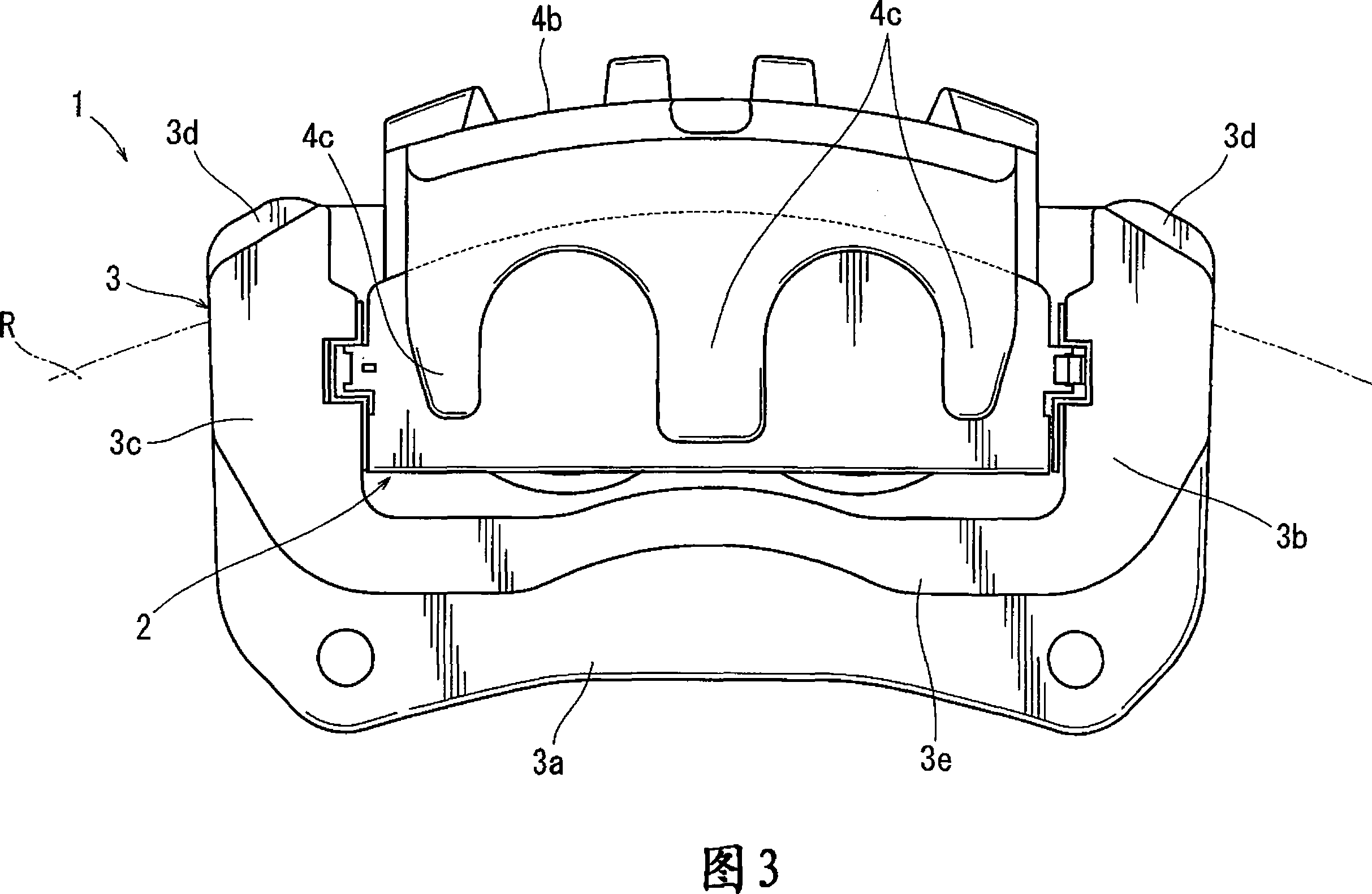
[0023] Each of the additional features and teachings disclosed above and below can be used alone or in combination with the other features and teachings to provide improved disc brakes. Representative examples of the present invention using these additional features and teachings alone or in combination with each other will now be described in detail with reference to the accompanying drawings. This detailed description is only intended to teach further details for practicing preferred aspects of the teachings to those of ordinary skill in the art, and is not intended to limit the scope of the invention. Only the claims define the scope of the claimed invention. Therefore, combinations of features and steps disclosed in the following detailed description are not necessary to practice the invention in its broadest sense, but are merely used to specifically describe representative examples of the invention. Furthermore, the individual features of the representative examples and...


PUM


Abstract

One aspect of the invention includes a disc brake including a pad and a supporting member movably supporting the pad. The supporting member includes a pair of torque receiving portions adjacent to ends of the pad for regulating movement of the pad in two circumference directions of a disc rotor. A first bias member is disposed between the pad and the supporting member and is capable of biasing the pad at all times from a side of the one torque receiving portion toward the other torque receiving portion. A second bias member is disposed between the pad and the supporting member and is capable of biasing the pad toward the other torque receiving portion only when the pad moving toward the one torque receiving portion. In addition, the first bias member and the second bias member bias different portions of the pad.

Description

[0001] Related Application Cross Reference [0002] This application claims priority from Japanese Patent Application Serial No. 2006-334253, the contents of which are hereby incorporated by reference into this application. technical field [0003] The present invention relates to a disc brake comprising a pad pushed onto a disc rotary and comprising a support member for movably supporting the pad. More particularly, the present invention relates to a disc brake having a structure for suppressing rattling noise, which may be generated when a pad hits a torque receiving portion formed in a support member during braking. Background technique [0004] A disc brake described in JP-A-10-331883 discloses a disc brake having a pair of pads and a support member for supporting the pads. The support member is provided with two pairs of torque receiving portions. The torque receiving portion is adjacent to both ends of each pad in the circumferential direction of the disc rotor. And...

Claims


Application Information

Patent Timeline
Patent Type & Authority Applications(China)
IPC IPC(8): F16D65/097
CPCF16D65/0978F16D65/0977F16D65/095
Inventor 竹尾祐一和气正树
Owner ADVICS CO LTD
Why Eureka
Try Eureka