Novel electronic expansion valve

An electronic expansion valve, a new type of technology, applied in the direction of valve lift, valve details, valve devices, etc., can solve the problems of low control precision and complex structure, and achieve the effect of accurate flow area

Inactive Publication Date: 2008-06-18
TIANJIN UNIVERSITY OF SCIENCE AND TECHNOLOGY
View PDF0 Cites 6 Cited by
  • Summary
  • Abstract
  • Description
  • Claims
  • Application Information

AI Technical Summary

Problems solved by technology

The electronic expansion valve with stepping motor as the executive part has high control precision, but the structure is complex; the electronic expansio

Method used


Image

  • Novel electronic expansion valve
  • Novel electronic expansion valve

Examples


Embodiment Construction

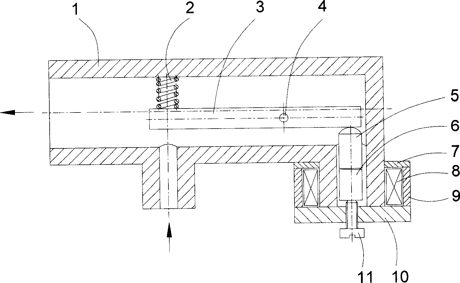
[0015] Liquid refrigerant enters the electronic expansion valve from the liquid inlet. When refrigeration, air conditioning, and heat pump systems require a large refrigerant flow rate, the coil 8 in the electronic expansion valve does not pass current, and the magnetostrictive material drive rod 6 of the electronic expansion valve is at figure 1 In the state shown in , the flow area of ​​the refrigerant is the largest at this time.

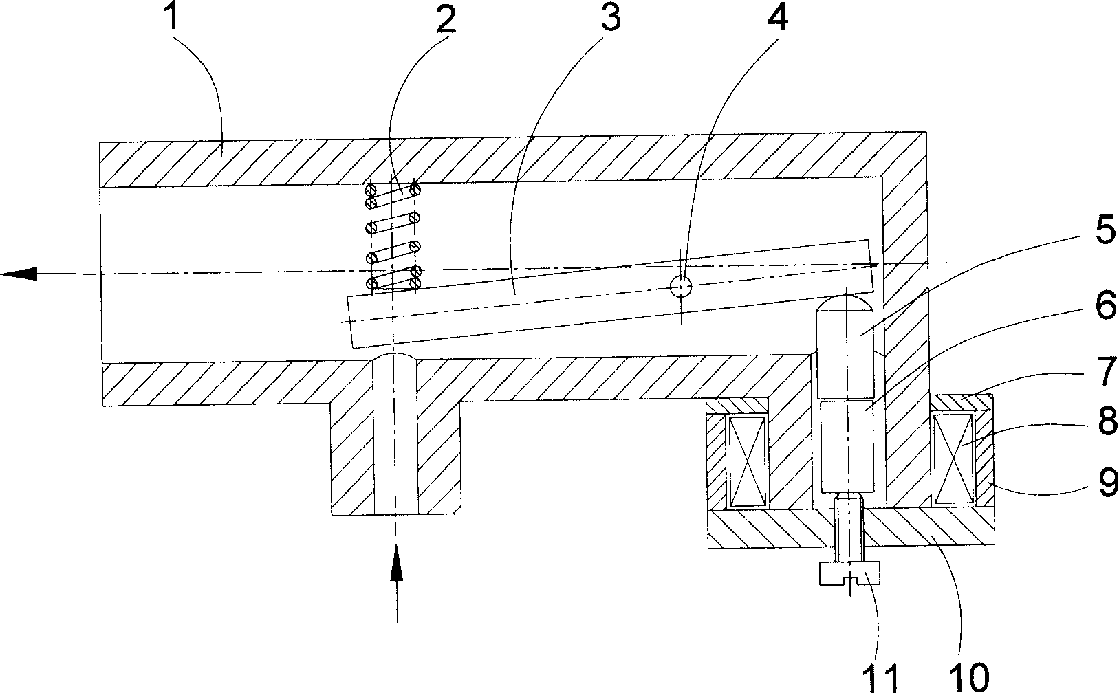
[0016] When the operating conditions of refrigeration, air conditioning, and heat pump systems change, and the flow rate of the refrigerant needs to be adjusted to a small value, a current is passed through the coil 8 to generate a magnetic field. The drive rod 6 of magnetostrictive material is elongated in the axial direction under the action of the magnetic field, pushing the displacement transmission rod 5 to move upward, so that the valve rod 3 rotates counterclockwise along the rotating shaft 4, the distance between the valve rod 3 and the l...


PUM


Abstract

The invention relates to a novel electronic expansion valve used for cooling, air conditioning and hot pump system. The invention aims at improving a drive mode and a displacement transmitting structure of the electronic expansion valve. The electronic expansion valve of the invention generates a magnetic field to lead a magnetostriction material drive rod to stretch to put a displacement transmitting rod (5) to move when a current is pumped into a loop (8). The displacement transmitting rod (5) then pushes a pushing valve rod (3) to move along a rotary shaft(4) to lead the distance between the valve rod (3) and a liquid inlet; thereby leading the current area of a freezing medium to be changed. Adjusting the current in the loop (8) can control the flow of the freezing medium.

Description

technical field [0001] The invention relates to an electronic expansion valve used in refrigeration, air conditioning and heat pump systems. The flow rate of refrigerant to the evaporator may be controlled according to the temperature of the refrigerant. Background technique [0002] The basic components of mechanical compression refrigeration, air conditioning, and heat pump systems are compressors, condensers, expansion valves, and evaporators. Refrigerant evaporates, gasifies and refrigerates under low pressure in the evaporator. The refrigerant vapor is boosted by the compressor and transported to the condenser. It releases heat, condenses and liquefies under high pressure in the condenser. The liquid refrigerant enters the evaporator after being depressurized by the expansion valve. next cycle. [0003] The role of the expansion valve is to control the flow of refrigerant flowing from the condenser to the evaporator, so that the flow of refrigerant entering the evapor...

Claims


Application Information

Patent Timeline
IPC IPC(8): F16K1/16F16K31/06F25B41/06
CPCF25B2341/065F25B41/06Y02B30/72Y02B30/70F25B41/34
Inventor 陈东谢继红
Owner TIANJIN UNIVERSITY OF SCIENCE AND TECHNOLOGY
Why Eureka
Try Eureka