
Interdiction method and device with press pipe

A technology for blocking equipment and pipelines, which is applied in the direction of mechanical equipment, pipe components, pipes/pipe joints/fittings, etc., can solve the problems of no literature reports, pipeline explosion, large economic losses, etc., and achieve good promotion and use value and safety High, low-cost effect

Inactive Publication Date: 2008-06-18
济南市公明新技术开发有限公司 +1
View PDF1 Cites 10 Cited by
  • Summary
  • Abstract
  • Description
  • Claims
  • Application Information

AI Technical Summary

Problems solved by technology

[0002] In the prior art, if it is necessary to repair, connect branch pipes, replace valves or replace pipelines for industrial infusion or gas pipelines that are normally operated under pressure, the construction must be done under pressure, that is, the pipeline can only be repaired and connected. Branch pipes, replacement of valves or replacement of pipelines, the currently known problems caused by the suspension of production of pipelines are 1) huge economic losses, such as urban water pipelines, gas pipelines, natural gas pipelines, etc. 2) For production enterprises, water and gas cutoffs will affect production; 3) Gas pipeline maintenance, takeover, replacement of valves or replacement of pipelines for gas pipelines, and gas replacement treatment for pipelines after construction , usually use inert gas for purging, otherwise serious accidents such as pipeline explosion will occur
As far as the present is concerned, there is no literature report in the world that the pipeline is under pressure and does not stop production.

Method used


Image

  • Interdiction method and device with press pipe
  • Interdiction method and device with press pipe
  • Interdiction method and device with press pipe

Examples


Embodiment Construction

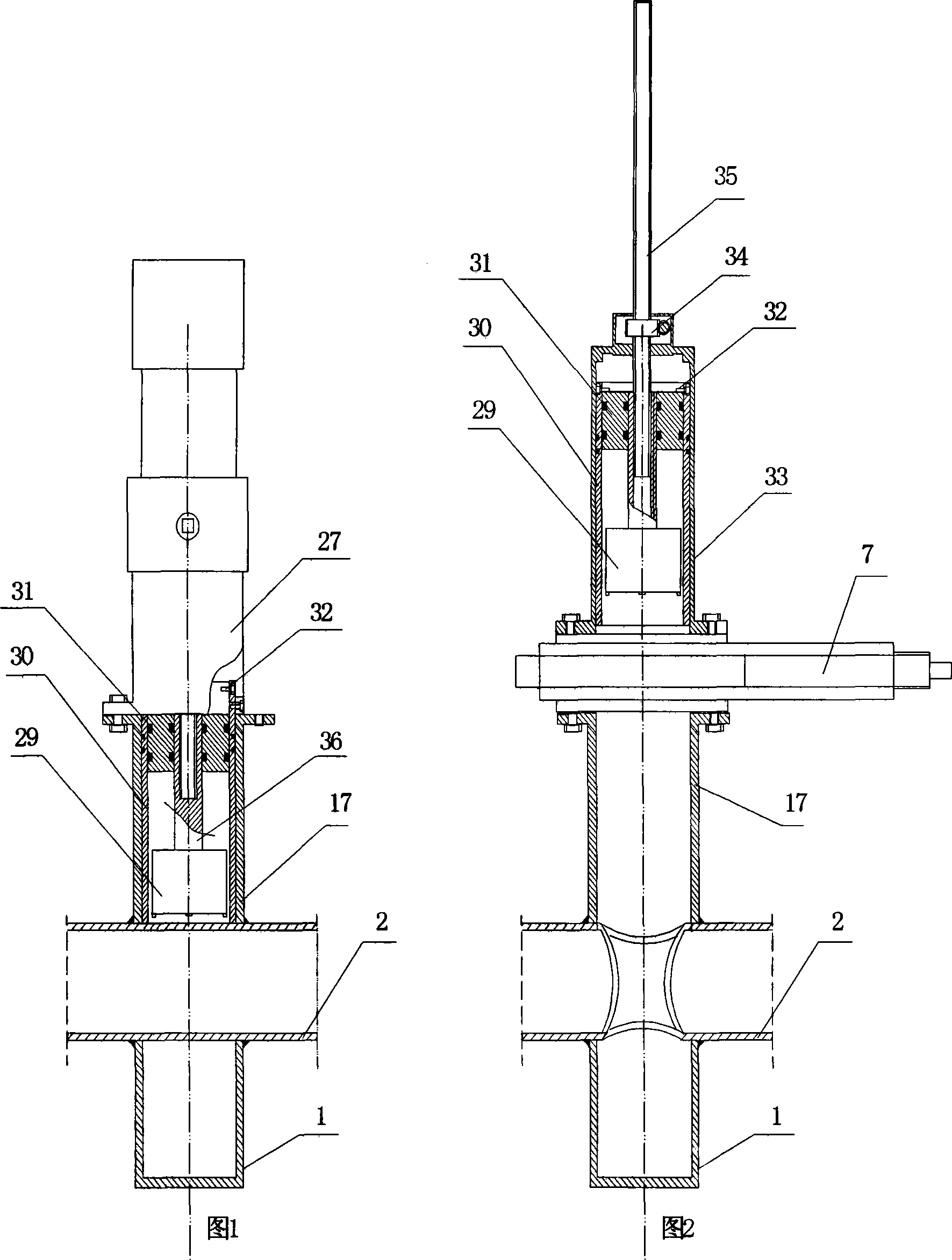
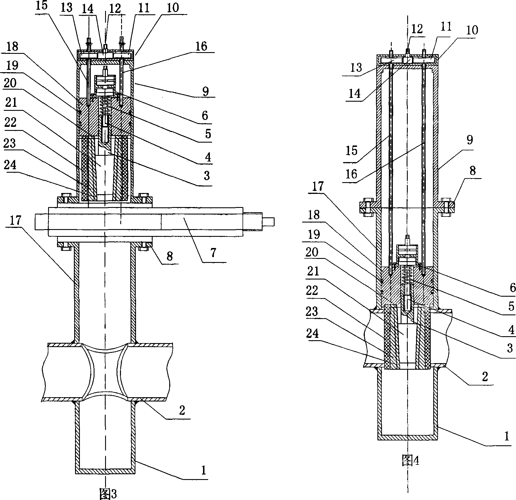
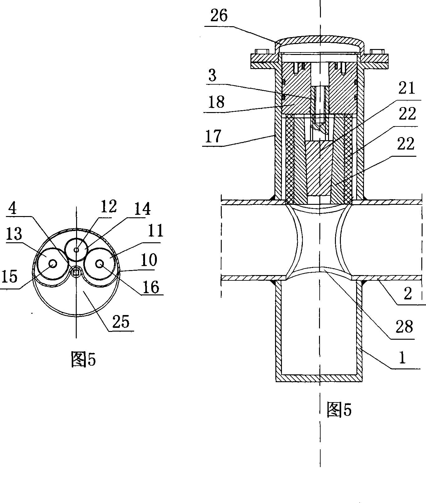
[0022] The present invention is described in detail below with reference to accompanying drawings 1-6 of the specification.

[0023] The blocking method of the pressurized pipeline of the present invention, its specific blocking steps are as follows:

[0024] 1) As shown in accompanying drawing 1, divide up and down welded process pipe 17 and slag collection pipe 1 on the pipeline under pressure that needs to be repaired or replaced;

[0025] 2) As shown in accompanying drawing 1, first insert the bushing 30 in the process pipe 17, then insert the milling cutter head 29 with the milling cutter head sealing piston 31 in the bushing 30, and then insert the milling cutter head 29 on the flange 8 upper part of the process pipe 17 Install the power head 27, the power head on the top of the pressurized pipe opener will insert the milling cutter head 29 with the bushing 30 and the milling cutter head sealing piston 31 into the process pipe 17, start the power head 27 to drive the mil...


PUM


Abstract

The invention provides an interdiction method and device for a pressurized pipeline. The device consists of a slag collecting tube, a process tube, a reblading device, a pipeline pressurized tapping machine and a pipeline blocker. The pressurized pipeline consists of an upper welding process tube, a lower welding process tube and the slag collecting tube. The process tubes are arranged above the slag collecting tube. The upper end of the process tube is provided with a flange and is connected with flanges at the lower ends of the tapping machine, the reblading device and the pressurized pipeline blocker through the flange. Compared with the prior art, the welding type pressurized pipeline blocker has excellent effects of realizing the pressurized connection of branch pipes and the pressurized connection of bypasses, the pressurized replacement of valves, the pressurized replacement of pipelines, as well as the maintenance and replacement of the pressurized pipelines, with no need of depressurizing pipelines or stopping production and no effect on the normal medium transmission of the pipelines. The invention is convenient, portable and has the advantages of low cost and high security, solving the unsolved world difficulty of the pipeline maintenance and pressurized construction, thus having excellent popularization and using values.

Description

1. Technical field [0001] The invention relates to a pressurized maintenance or pipe connection technology of a welded pipeline, in particular to a pressurized pipeline blocking method and its blocking equipment. 2. Background technology [0002] In the prior art, if it is necessary to repair, connect branch pipes, replace valves or replace pipelines for industrial infusion or gas pipelines that are normally operated under pressure, the construction must be done under pressure, that is, the pipeline can only be repaired and connected. Branch pipes, replacement of valves or replacement of pipelines, the currently known problems caused by the suspension of production of pipelines are 1) huge economic losses, such as urban water pipelines, gas pipelines, natural gas pipelines, etc. 2) For production enterprises, water and gas cutoffs will affect production; 3) Gas pipeline maintenance, takeover, replacement of valves or replacement of pipelines for gas pipelines, and gas replac...

Claims


Application Information

Patent Timeline
IPC IPC(8): F16L55/18F16L55/10
Inventor 钊洪智李长年钊田
Owner 济南市公明新技术开发有限公司
Learn More