Sound localization method and system

A sound source localization and sound source technology, applied in the field of localization, can solve the problems of reducing the utilization rate of basic acquisition devices, waste of resources, etc., and achieve the effect of improving utilization rate and reducing waste

Active Publication Date: 2008-06-18
BEIJING VIMICRO ARTIFICIAL INTELLIGENCE CHIP TECH CO LTD
View PDF0 Cites 33 Cited by
  • Summary
  • Abstract
  • Description
  • Claims
  • Application Information

AI Technical Summary

Problems solved by technology

[0011] However, when using at least two basic acquisition devices for sound source localization, since each basic acquisition devi

Method used


Image

  • Sound localization method and system
  • Sound localization method and system
  • Sound localization method and system

Examples


no. 1 example

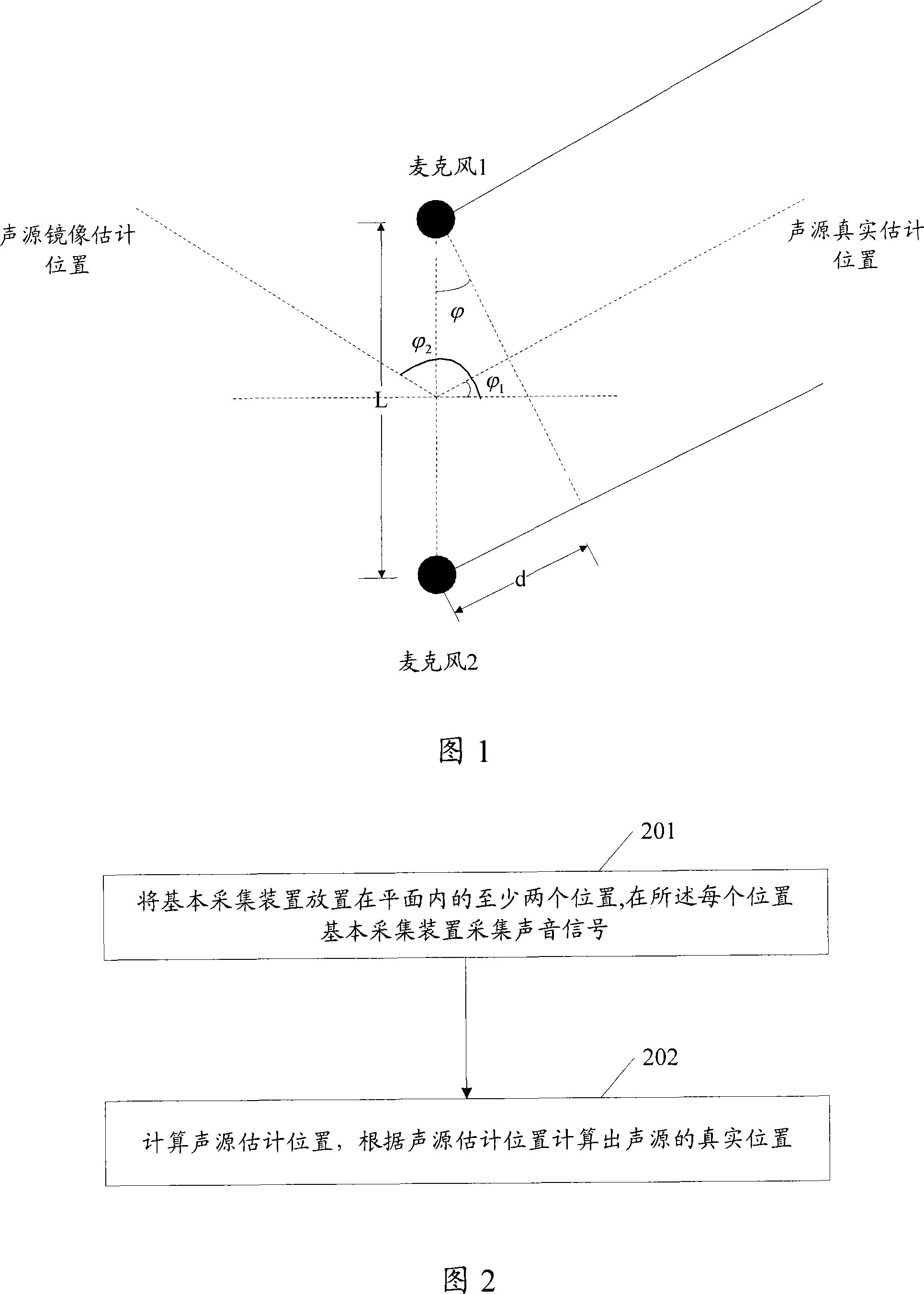
[0031] Fig. 2 is a flowchart of a sound source localization method provided by an embodiment of the present invention. as shown in picture 2:

[0032] Step 201: Place the basic collection device on at least two positions in a plane, where the basic collection device collects a set of sound signals from a sound source, and the plane is the basic collection device and the sound source common plane.

[0033] Placing the basic acquisition device in at least two positions in the plane in this step can be achieved by:

[0034] The basic collection device is rotated in one direction in the plane with its center as the center of a circle, and every time it rotates to a preset angle, the angle is used as a position for the basic collection device to collect sound signals.

[0035] Wherein, the said rotation according to one direction may be a 360-degree counterclockwise rotation at a uniform speed.

[0036] Step 202: Calculate the estimated position of the sound source according to ...

no. 2 example

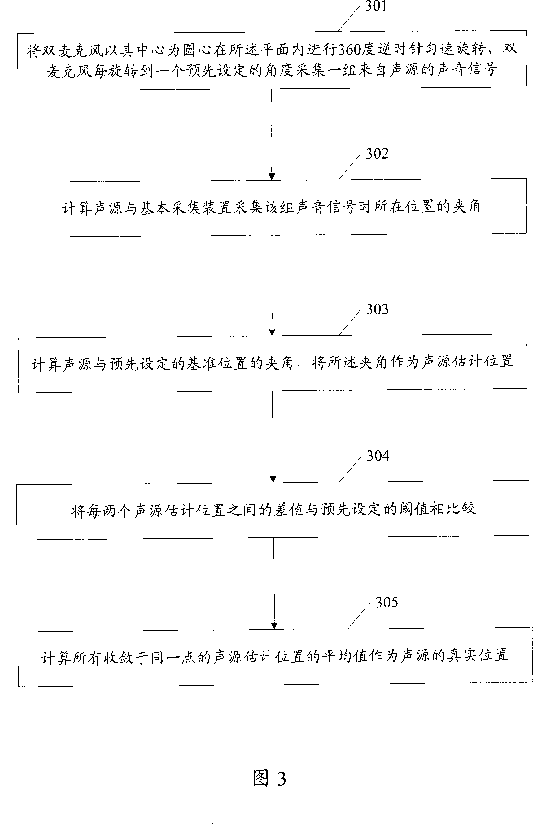
[0042] In this embodiment, the cycle of rotating the dual microphones is T, that is, the time used for rotating 360 degrees is T, the sampling rate of the microphone acquisition signal is 8kHz, and the length of one frame of sound signal is M, that is, the number of sampling points in each frame for M.

[0043] Fig. 3 is a flowchart of a sound source localization method provided by an embodiment of the present invention. As shown in Figure 3:

[0044] Step 301: The dual microphones are rotated 360 degrees counterclockwise in the plane with the center as the center of a circle at a constant speed, and each time the dual microphones rotate to a preset angle, a group of sound signals from the sound source is collected.

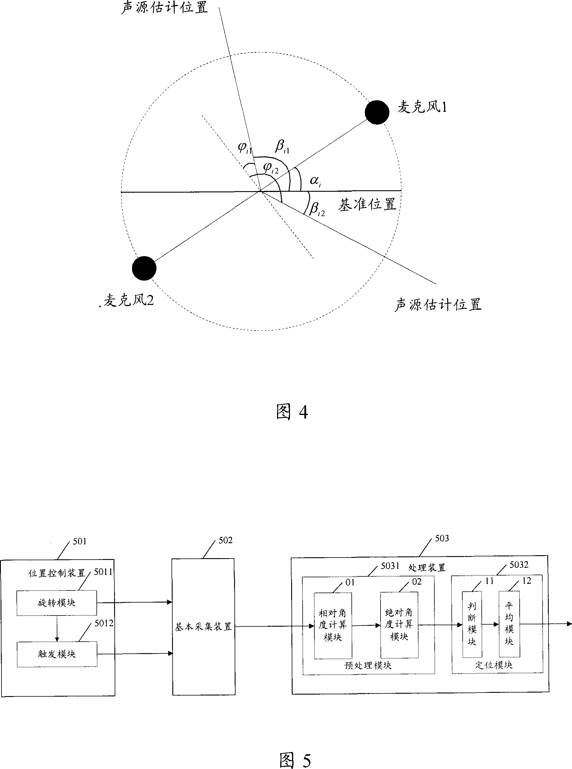
[0045] The geometric diagram of the sound source localization method provided by the embodiment of the present invention is shown in Figure 4:

[0046] In this embodiment, the dual-microphone array rotates counterclockwise with the preset reference position as ...

no. 3 example

[0084] Fig. 5 is a structural diagram of a sound source localization system provided by an embodiment of the present invention. As shown in Figure 5:

[0085] The sound source localization system provided by the embodiment of the present invention includes: a position control device 501 , a basic collection device 502 and a processing device 503 .

[0086] The position control device 501 is used to place the basic collection device 502 in at least two positions in the plane, and send a collection message to the basic collection device 502 at each position, and the plane is where the basic collection device 502 is located in the plane. The plane in which the sound sources are common.

[0087] The position control device 501 includes: a rotation module 5011 and a trigger module 5012 .

[0088] The rotation module 5011 is used to control the basic collection device 502 to rotate in one direction in the plane with the center of the basic collection device 502 as the center of a ...


PUM


Abstract

The embodiment of the invention discloses a sound-source location method and system e. A basic collection device is positioned on at least two locations in a plane; the basic collection device collects a group of audio signals from the sound source at each location; the plane is the common plane where both the basic collection device and the sound source are arranged; the estimated location of a group of sound source is calculated according to the collected each group of audio signals; the actual location of the sound source is calculated according to the estimated location of the sound source which is convergent to the same point. The audio signals are collected through changing the location of the basic collection device; the actual location of the sound source is calculated according to the collected multiple groups of audio signals; the invention completes the location of the sound source which is realized in the current technology by using at least two basic collection devices; the invention improves the utilization efficiency of the basic collection device.

Description

technical field [0001] The invention relates to positioning technology, in particular to a sound source localization method and system. Background technique [0002] At present, the positioning technology has been more and more widely used, and the position of the target can be determined according to the information from the target by using the positioning technology. Sound source localization is an important technology in positioning technology. The sound signals from the sound source arrive at the collection device at different times. By estimating the time difference between the sound signals collected by the collection device, and according to the estimated time difference and the collection device itself The size and geometric relationship of the structure can calculate the position of the sound source relative to the acquisition device. Sound source localization is widely used in various fields. For example, in monitoring, through sound source localization, the camer...

Claims


Application Information

Patent Timeline
IPC IPC(8): G01S5/20
Inventor 张晨
Owner BEIJING VIMICRO ARTIFICIAL INTELLIGENCE CHIP TECH CO LTD
Why Eureka
Try Eureka