
Serial transmission system, a method for automatically correcting signal quality of serial transmission system, and port

A technology for serial transmission and signal quality, which is applied in the field of serial transmission systems and can solve problems such as increasing the signal level.

Inactive Publication Date: 2008-06-18
FUJITSU LTD
View PDF1 Cites 5 Cited by
  • Summary
  • Abstract
  • Description
  • Claims
  • Application Information

AI Technical Summary

Problems solved by technology

As a result, the port at the other end increases the signal level, causing a latch-up

Method used


Image

  • Serial transmission system, a method for automatically correcting signal quality of serial transmission system, and port
  • Serial transmission system, a method for automatically correcting signal quality of serial transmission system, and port
  • Serial transmission system, a method for automatically correcting signal quality of serial transmission system, and port

Examples


Embodiment approach

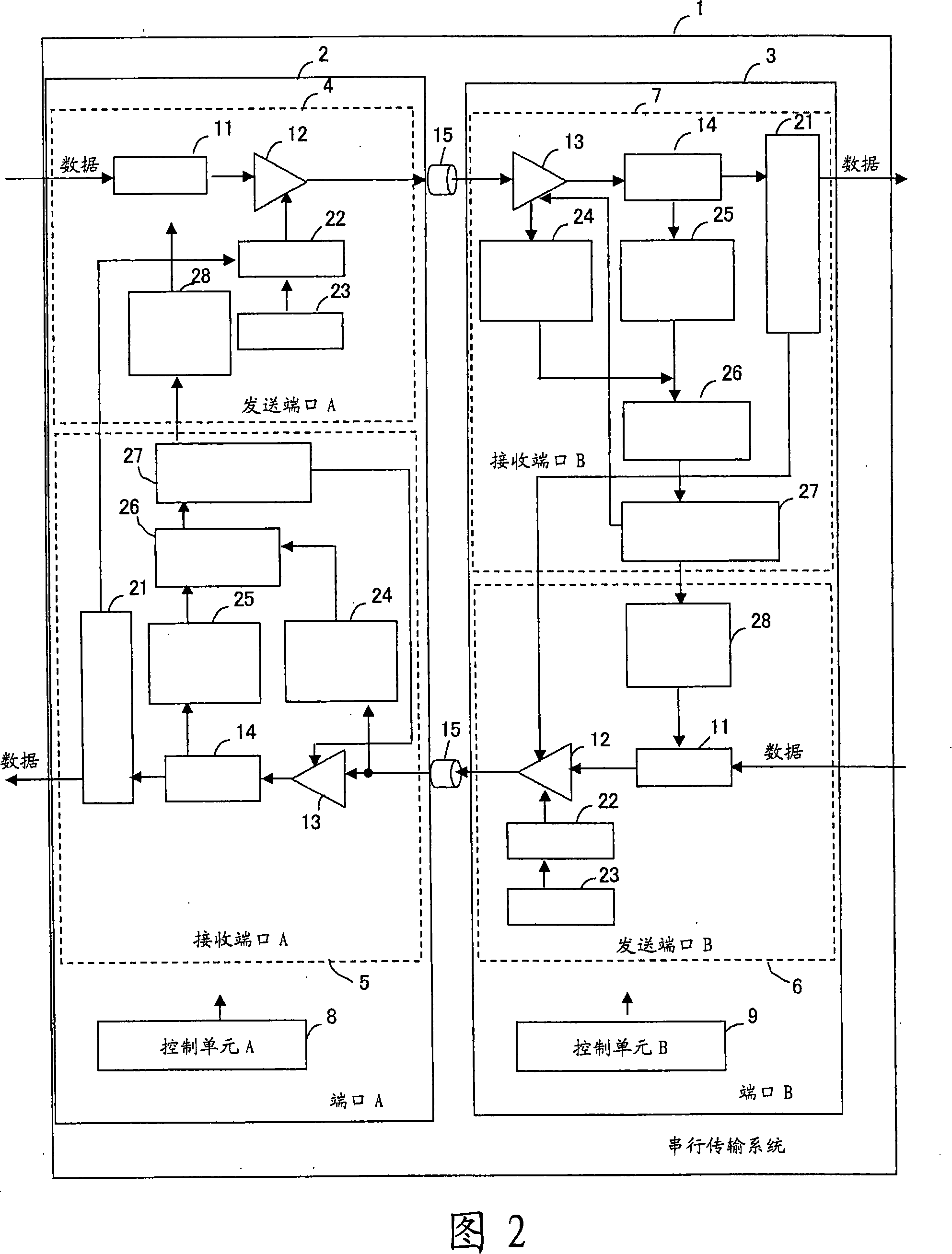
[0026] Figure 2 is a block diagram of a serial transmission system. The serial transmission system 1 includes ports A2 and B3. The serial transmission system 1 is an example of an opposed serial transmission system in which ports A2 and B3 are connected in a one-to-one correspondence. In the serial transmission system 1, the transmission mode of the fiber channel is used.

[0027] The port A2 includes a sending port A4, a receiving port A5 and a control unit A8. When receiving the correction request data from the port B3, the port A2 changes the output characteristic of the transmission unit 12 in the transmission port A4. The port A2 also outputs the input data to the transmission path 15 as serial data. The port A2 also outputs received data other than correction request data from the transmission path 15 . Port A2 also measures signal quality when receiving data to determine if correction is required. When correction is required, port A2 sends correction request data t...


PUM


Abstract

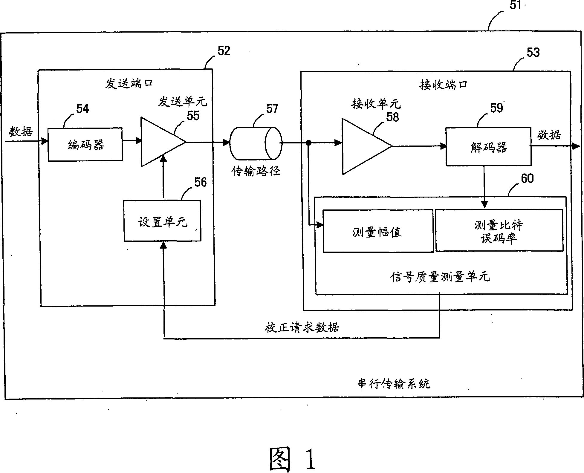
A serial transmission system performs data transfer between a first port and a second port via a transmission path. The first port includes a receiving unit that receives data, a signal-quality measuring unit that measures the signal quality of receive data, a correction-request-data generating unit that generates correction request data for correcting output characteristics of the second port on the basis of a result of the measurement, and a sending unit that sends the generated correction request data. The second port includes a sending unit that sends data, a receiving unit that receives the correction request data from the first port, and a setting unit that changes settings of output characteristics of the sending unit on the basis of the received correction request data.

Description

technical field [0001] The present invention relates to a serial transmission system in which a mismatch of electrical characteristics in a transmission system, such as in a disk drive, is dynamically detected by a signal receiving device and signaled to a signal transmitting device by sending information relating to the mismatch to a signal transmitting device Make corrections. Background technique [0002] Recently, due to the increase in the amount of data handled by the server, high-speed data transmission and extended connection distance are required in the interface of the storage unit connected to the server. Accordingly, Fiber Channel has been increasingly adopted in server systems and the like instead of the existing Small Computer System Interface (SCSI). The T11 committee of the American National Standards Institute develops Fiber Channel standards. In Fiber Channel, a maximum transmission distance of 10 km and high-speed data transmission over long distances ar...

Claims


Application Information

Patent Timeline
Patent Type & Authority Applications(China)
IPC IPC(8): G06F13/40
CPCH04L1/0016H04L1/0001H04L25/03343H04L1/20H04B3/04H04L1/00
Inventor 河本正和
Owner FUJITSU LTD
Learn More