Ink-jetting head fluid supply device and ink-jetting head cleaning device

A technology of liquid feeding device and cleaning device, applied in printing devices, printing and other directions, can solve the problems of hindering liquid feeding, increasing pressure loss, and breaking the liquid feeding path, so as to reduce flow resistance, reduce pressure loss, and reduce contact area. small effect

Active Publication Date: 2008-06-18
ISHII HYOKI
View PDF7 Cites 10 Cited by
  • Summary
  • Abstract
  • Description
  • Claims
  • Application Information

AI Technical Summary

Problems solved by technology

Therefore, it is necessary to make the liquid delivery path high-strength, which not only incurs an increase in manufacturing cost, but also tends to cause damage to the liquid delivery path, and increases the pressure loss to cause waste.
Therefore, although this method may be applied to liquid materials with low viscosity (such as liquid materials with a viscosity less than 5 cp), it may hinder the delivery of high-viscosity liquid materials (such as liquid materials with a viscosity above 5 cp or above 6 cp). Liquid and other fatal problems
Therefore, the structure is complica

Method used


Image

  • Ink-jetting head fluid supply device and ink-jetting head cleaning device
  • Ink-jetting head fluid supply device and ink-jetting head cleaning device
  • Ink-jetting head fluid supply device and ink-jetting head cleaning device

Examples


no. 1 approach

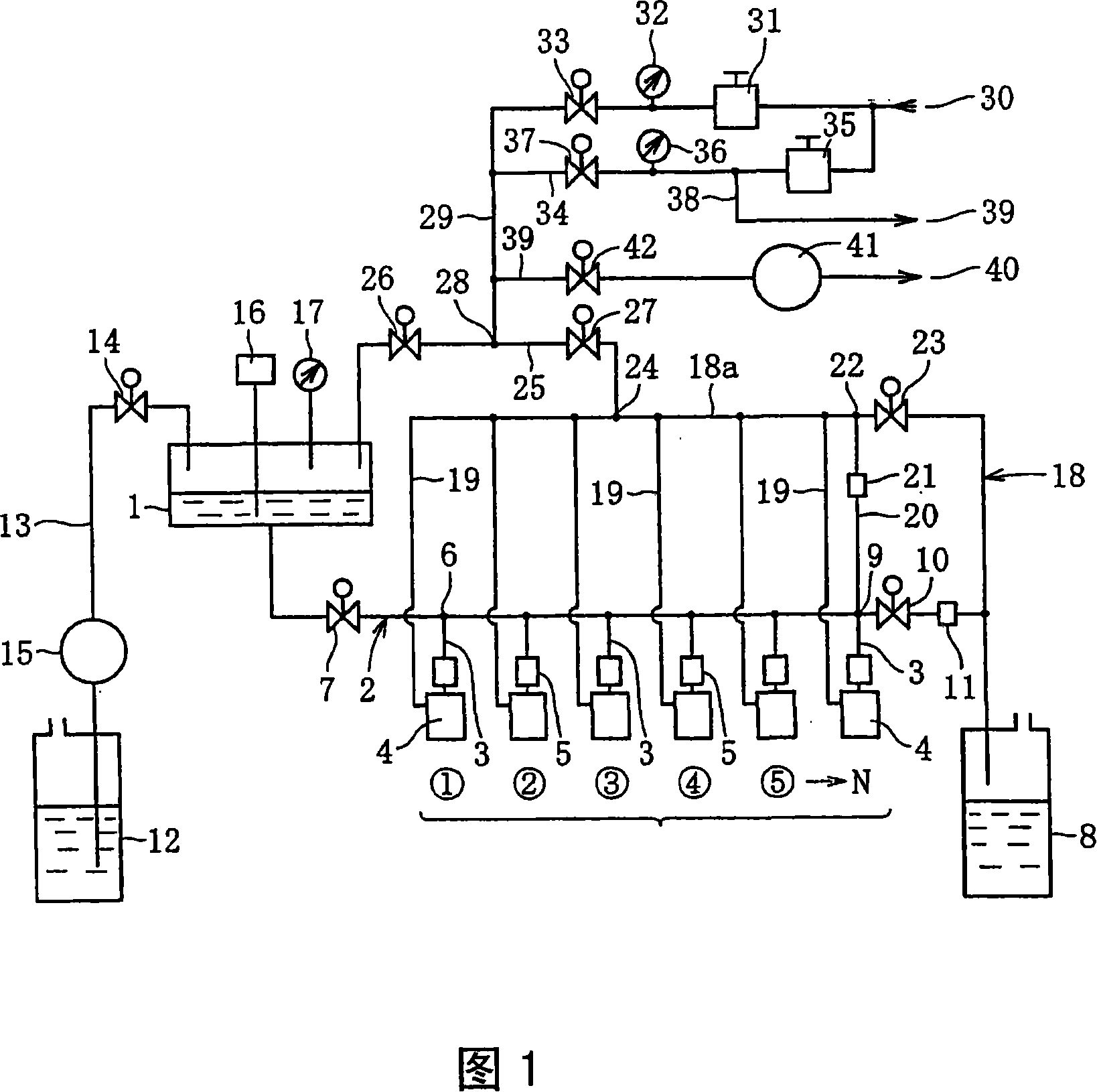
[0111] FIG. 1 illustrates an inkjet head liquid feeding device according to a first embodiment of the present invention. As shown in FIG. 1, in the inkjet head liquid delivery device of the first embodiment, the ink tank 1 storing the liquid material communicates with the common liquid delivery pipeline 2 extending horizontally below the ink tank 1, and, A plurality of independent liquid delivery pipelines 3 are connected at equal intervals to the common liquid delivery pipeline 2 . These independent liquid-feeding pipelines 3 extend downward from the common liquid-feeding pipeline 2, and the lower ends of each independent liquid-feeding pipeline 3 are respectively connected to the inkjet head 4 (the liquid storage part inside it), and in these vertical directions On the way, degassing units 5 for degassing bubbles such as air in the liquid material are respectively provided. In addition, in the illustration, six inkjet heads 4 are provided, but n number of six or more may be...

no. 2 approach

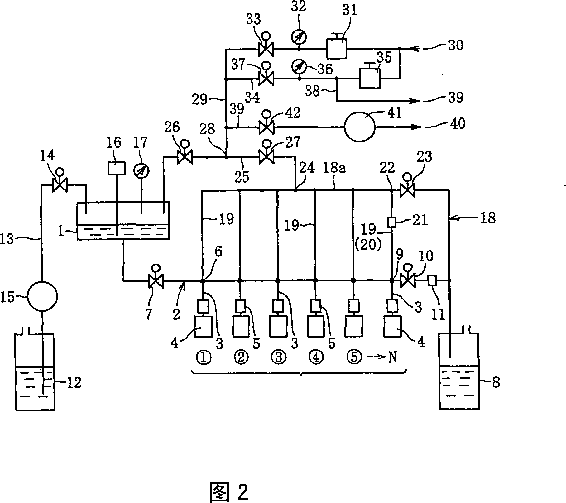
[0122] FIG. 2 illustrates an inkjet head liquid feeding device according to a second embodiment of the present invention. As shown in Figure 2, the inkjet head liquid delivery device of this second embodiment differs from the inkjet head liquid delivery device of the first embodiment above in two points: one is that the liquid is supplied from the side of the common diffuser pipeline 18 Each lower end of each independent air-dispersing pipeline 19 extending downwards from road pipeline 18a communicates with each joint of the common liquid-feeding pipeline 2 and each independent liquid-feeding pipe 3; Liquid and gas pipeline 20. The other components are the same as those of the inkjet head liquid feeding device of the above-mentioned first embodiment, and thus the same reference numerals are used for the components common to both, and redundant descriptions are omitted.

[0123] According to the inkjet head liquid delivery device of the second embodiment, the gas flowing in th...

no. 3 approach

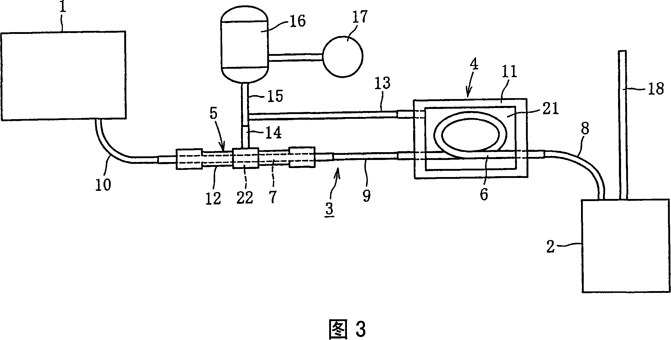
[0126] 3 to 5 illustrate an inkjet head liquid feeding device according to a third embodiment of the present invention. As shown in FIG. 3 , the inkjet head liquid supply device of the third embodiment has a liquid supply system for transporting the liquid material from the ink reservoir 1 storing the liquid material to the inkjet head 2 (internal liquid reservoir). The path 3 is provided with a first degassing unit 4 and a second degassing unit 5 at two places on the way of the liquid feeding path 3 . The liquid delivery path 3 is composed of two synthetic resin degassing tubes (hereinafter referred to as first and second degassing tubes 6 and 7 ) with air permeability and a single internal flow path, and an air-impermeable and single internal flow path. Three liquid-feeding pipes (hereinafter referred to as first to third liquid-feeding pipes 8, 9, 10) made of metal are connected. In this case, the first and second degassing pipes 6 and 7 are formed by cutting a pipe (trade...


PUM

PropertyMeasurementUnit
The inside diameter ofaaaaaaaaaa
Outer diameteraaaaaaaaaa
Viscosityaaaaaaaaaa

Abstract

The present invention provides an inkjet head liquid feeding device and an inkjet head cleaning device, which do not cause the complexity of the pipeline and do not cause gas to remain in the liquid delivery pipeline when the liquid material is supplied to the inkjet head, Furthermore, the hydraulic pressure of the liquid material supplied to each inkjet head is made uniform. Each independent liquid-feeding pipeline (3) used for supplying the liquid material communicated with a plurality of ink-jet heads (4) respectively is connected to a common liquid-feeding pipe communicated with an ink tank (1) storing a kind of liquid material On the road (2), and each independent diffuser pipeline (19) that can circulate gas is connected to the bypass pipeline (18a) (common diffuser pipeline 18) that can be opened and closed to the atmosphere. The gas pipeline (19) and the common liquid delivery pipeline (2) communicate with each connecting portion of each independent liquid delivery pipeline (3), or each inkjet head (4), or both of them respectively.

Description

technical field [0001] The present invention relates to an inkjet head liquid feeding device configured to feed liquid material from an ink tank to an inkjet head, and for properly absorbing and removing impurities adhering to the liquid material ejection port and its surroundings of the inkjet head inkjet head cleaning device. Background technique [0002] In recent years, when printing with ink on printing media such as paper, when forming an alignment film or coating UV ink on a substrate (transparent substrate) such as a liquid crystal display, or coating a filter substrate on an organic EL display substrate, In the case of a color device, the so-called inkjet method using an inkjet head has been widely used. [0003] In an inkjet printer (including an alignment film forming device and a coating device; hereinafter the same) that adopts this inkjet method, a device for feeding a liquid material from an ink tank to an inkjet head (specifically, an inkjet head) is provide...

Claims


Application Information

Patent Timeline
IPC IPC(8): B41J2/175
CPCB41J2/175B41J2/16585B41J2/16535B41J2/1721B41J2/17596B41J29/393
Inventor 中野辉幸小泽康博
Owner ISHII HYOKI
Why Eureka
Try Eureka