
Liquid crystal panel drive circuit and LCD

A liquid crystal panel and driving circuit technology, applied in static indicators, instruments, nonlinear optics, etc., can solve the problems of screen flicker, liquid crystal shift, liquid crystal clamping screen flicker, etc., and achieve the effect of avoiding flicker.

Inactive Publication Date: 2008-06-25
INNOCOM TECH SHENZHEN +1
View PDF0 Cites 13 Cited by
  • Summary
  • Abstract
  • Description
  • Claims
  • Application Information

AI Technical Summary

Problems solved by technology

[0008] In order to solve the problem in the prior art that the liquid crystal clamping pressure tends to shift and cause the screen to flicker, it is necessary to provide a liquid crystal panel drive circuit that can automatically adjust the liquid crystal clamping pressure to prevent the screen from flickering
[0009] In addition, in order to solve the problem in the prior art that the liquid crystal clamping pressure tends to shift and cause screen flickering, it is also necessary to provide a liquid crystal display that can automatically adjust the liquid crystal clamping pressure to prevent screen flickering

Method used


Image

  • Liquid crystal panel drive circuit and LCD
  • Liquid crystal panel drive circuit and LCD
  • Liquid crystal panel drive circuit and LCD

Examples


Embodiment Construction

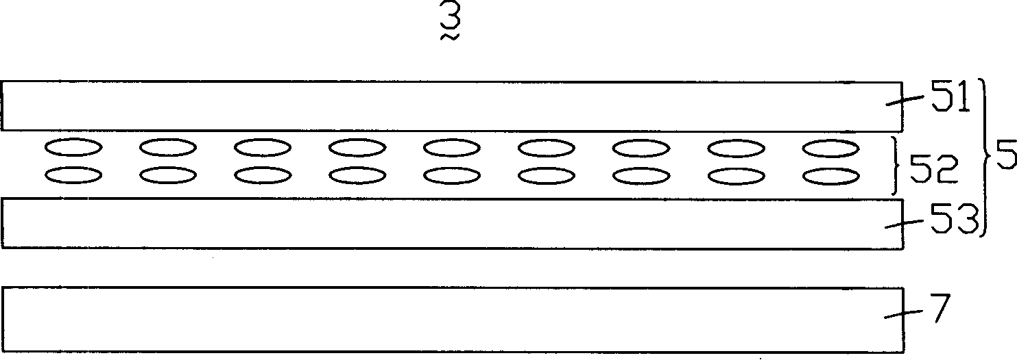
[0018] see figure 2 , is a schematic structural view of a preferred embodiment of the liquid crystal display of the present invention. The liquid crystal display 3 includes a liquid crystal panel 5 and a backlight module 7 for providing planar light to the liquid crystal panel 5 . The liquid crystal panel 5 includes an upper substrate 51 , a lower substrate 53 and a liquid crystal layer 52 sandwiched between the upper substrate 51 and the lower substrate 53 . The liquid crystal panel 5 is driven by a liquid crystal panel driving circuit (not shown).

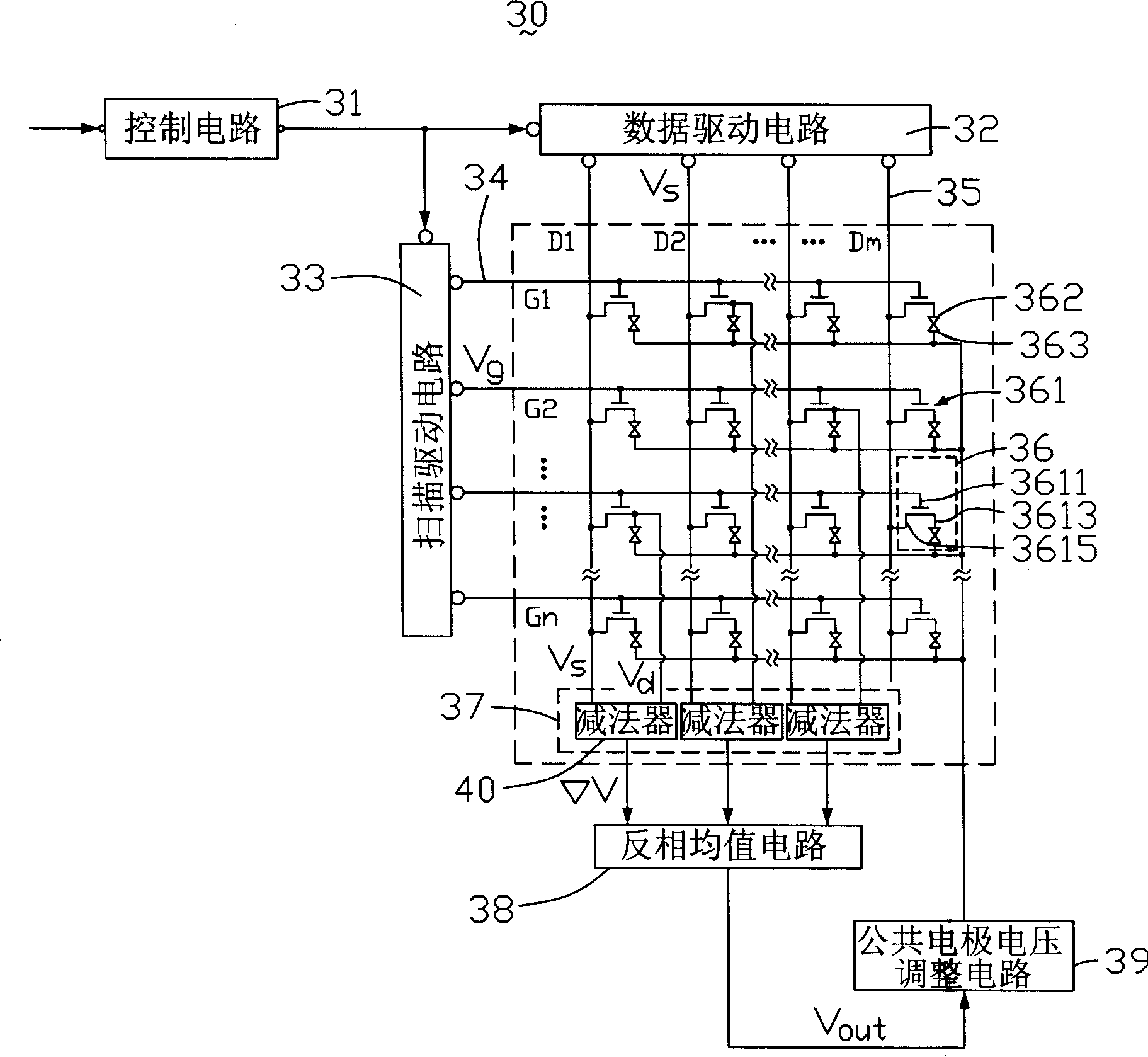
[0019] see image 3 , is a schematic circuit diagram of a liquid crystal panel drive circuit for driving the liquid crystal panel 5 . The liquid crystal panel driving circuit 30 includes a control circuit 31, a data driving circuit 32, a scanning driving circuit 33, a plurality of scanning lines 34 parallel to each other, and a plurality of data lines 35 parallel to each other and vertically insulated from the scanning lines ...


PUM


Abstract

The present invention relates to a liquid crystal panel driving circuit and a LCD. The liquid crystal panel driving circuit comprises a plurality of mutually parallel data lines, a plurality of mutually parallel scan lines in vertical insulated intersection with the data lines, a plurality of thin film transistors positioned at the intersections of the scan lines and the data lines, a plurality of pixel electrodes, a plurality of common electrodes, a comparison circuit and a reversed-phase mean circuit. The pixel electrodes are connected with the data lines via the thin film transistors. The common electrodes are arranged oppositely to the pixel electrodes. The comparison circuit compares the voltage of at least one pixel electrode and the voltage of the data lines connected with the pixel electrode. The reversed-phase mean circuit performs reversed-phase mean calculation to the voltage difference value gained by the comparison circuit, and feeds back the voltage mean value gained to the common electrodes. The liquid crystal panel driving circuit and the LCD can achieve the objective of adjusting liquid crystal clamp voltage automatically so as to avoid picture flicker.

Description

technical field [0001] The invention relates to a liquid crystal panel driving circuit and a liquid crystal display. Background technique [0002] Liquid crystal displays have been widely used in modern communication devices such as notebook computers, mobile phones, and personal digital assistants due to their advantages of thinness, lightness, low power consumption, and low radiation. [0003] Generally, a liquid crystal display includes a liquid crystal panel, a backlight module for providing planar light to the liquid crystal panel, and a driving circuit for controlling the display of the liquid crystal panel. The liquid crystal panel includes an upper substrate, a lower substrate and a liquid crystal layer sandwiched between the two substrates. [0004] see figure 1 , is a circuit structure diagram of a liquid crystal panel driving circuit in the prior art. The liquid crystal panel driving circuit 2 includes a control circuit 20, a common electrode voltage adjustment...

Claims


Application Information

Patent Timeline
IPC IPC(8): G02F1/1362G02F1/133G09G3/36
Inventor 黄丽娟
Owner INNOCOM TECH SHENZHEN
Features
  • Generate Ideas
  • Intellectual Property
  • Life Sciences
  • Materials
  • Tech Scout
  • Unparalleled Data Quality
  • Higher Quality Content
  • 60% Fewer Hallucinations
Learn More