Welding fixture of circuit board

A technique for welding jigs and circuit boards, which is applied in the direction of printed circuits, printed circuit manufacturing, and assembly of printed circuits with electrical components, and can solve problems such as looseness and inclination of electronic components 141

Active Publication Date: 2008-06-25
SHANGHAI MUNICIPAL ELECTRIC POWER CO
View PDF0 Cites 13 Cited by
  • Summary
  • Abstract
  • Description
  • Claims
  • Application Information

AI Technical Summary

Problems solved by technology

[0005] However, the pressure plate 12 is pivotally arranged on one side of the base 11. When the pressure plate 12 is pressed on the circuit board 14, the closer to the pivoted end The electronic component 141 contacts the pressed part 15 first, and the electronic component 141 farther away from the pivot end contacts the pressed part 15 later, that is, there is an angle between the pressed part 15 and the electronic component 141, so that the pressed parts 141 The parts 15 are not in contact with these electronic components 141 asynchronously; in short, the pressed parts 15 are not pressed vertically on the tops of the electronic components 141, so that the electronic components 141 are tilted, so that The electronic components 141 cannot only be tightly attached to the surface of the circuit board 14, which causes the electronic components 141 to become loose after soldering

Method used


Image

  • Welding fixture of circuit board
  • Welding fixture of circuit board
  • Welding fixture of circuit board

Examples


Embodiment Construction

[0031] Embodiments of the present invention are described below through specific examples, and those skilled in the art can easily observe other advantages and effects of the present invention from the content disclosed in this specification.

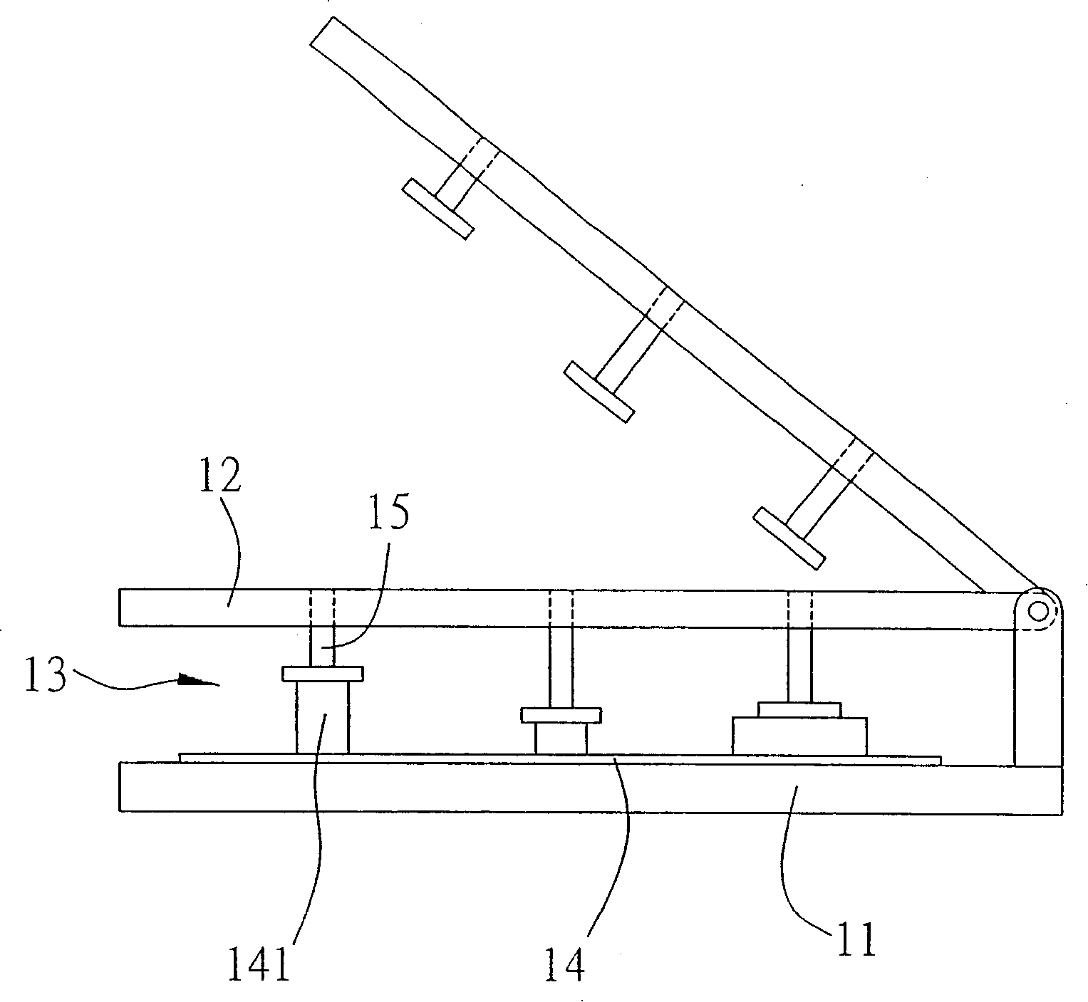
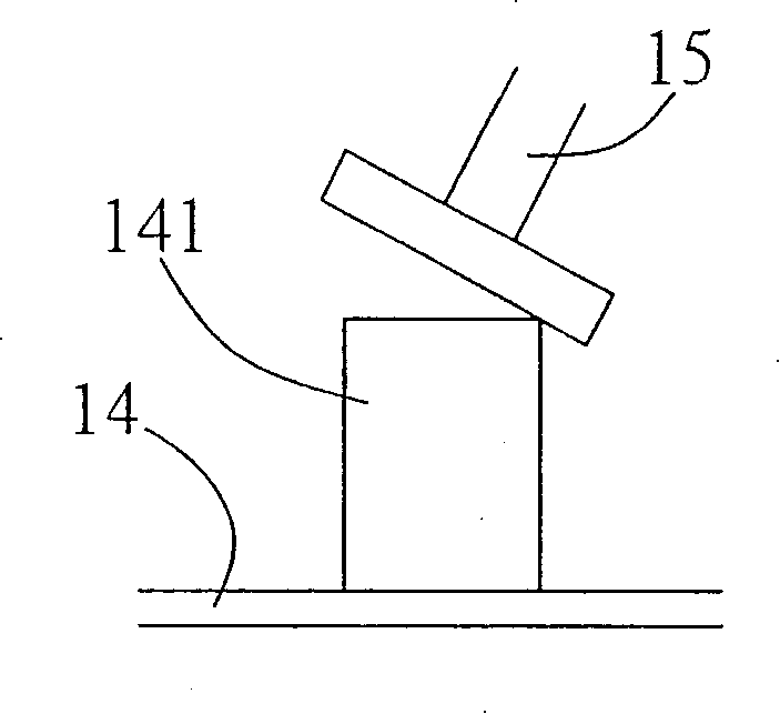
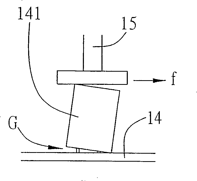
[0032] see Figure 3A and Figure 3B , is a schematic side view of the welding jig of the circuit board of the present invention; the welding jig 2 is used to clamp the electronic component 31 on the circuit board 3, and the welding jig 2 includes: a base 21; A movable plate 22, and a clamping space 23 is formed between the base 21 and the movable plate 22 for clamping the circuit board 3 with the electronic component 31; a pressing plate 24 slidingly arranged on the movable plate 22, A plurality of guide rods 25 are provided above the movable plate 22, and a guide sleeve 251 is sleeved on the guide rod 25 and fixed on the pressing plate 24, so that the pressing plate 24 slides up and down stably, and on the guide rod 25 On and betwee...


PUM


Abstract

The invention relates to a welding fixture of a circuit board, which is used for clamping electronic modules on the circuit board. The welding fixture comprises a pedestal; a mobile board which is articulated above the pedestal, thereby which forms a clamping space between the pedestal and the mobile board; a pressure plate which is arranged above the mobile board in sliding way and is provided with a plurality of ;moulding dies , wherein, the moulding dies pass through the mobile board, and extend into the clamping space, and vertically press and cling to the top parts of the electronic modules on the circuit board; and an orientation module which is arranged on the side of the mobile board and is used for positioning the pressure plate; therefore, the moulding dies are enabled to be vertically and downwards contacted with the top parts of the electronic modules, thereby avoiding the faults that the electronic modules cannot tightly cling to the circuit board which is caused by lateral thrust.

Description

technical field [0001] The invention relates to a soldering fixture for a circuit board, more specifically, a fixture for clamping a circuit board. Background technique [0002] Generally, the printed circuit board is soldered after inserting various electronic components on it, and the electronic component can be firmly and closely attached to the surface of the circuit board. After inserting the electronic component on the circuit board, clip Mounted on a welding fixture, the electronic component can be closely attached to the circuit board, and then the welding operation is performed. [0003] see figure 1 In the existing welding fixture, a pressing plate 12 is pivotally arranged above one side of a base 11, so that a sandwiching space 13 is formed between the base 11 and the pressing plate 12, and a circuit is sandwiched in the sandwiching space 13. Board 14, on which a plurality of electronic components 141 have been inserted and installed, such as capacitors, resisto...

Claims


Application Information

Patent Timeline
Patent Type & Authority Applications(China)
IPC IPC(8): H05K3/34H05K3/00
Inventor 杨逸民杨杰
Owner SHANGHAI MUNICIPAL ELECTRIC POWER CO
Why Eureka
Try Eureka