Oil-free chain

一种油链、套筒的技术,应用在传动链、输送机、运输和包装等方向,能够解决增加表面精加工加工负担、弯曲阻力变大、组装工时数多等问题,达到避免件数的增加、防止滑动接触磨损、防止链磨损的效果

Inactive Publication Date: 2008-07-02
TSUBAKIMOTO CHAIN CO
View PDF1 Cites 3 Cited by
  • Summary
  • Abstract
  • Description
  • Claims
  • Application Information

AI Technical Summary

Problems solved by technology

[0004] In the conventional sealing chain as described above, in order to seal the space between the bush and the outer link plate and to maintain the sealing effect of the lubricating oil injected between the pin and the bush, the ring member and the elastic seal ring are pressed together. The state is arranged between the sleeve and the outer link plate, and there is a pressing force through such a pressing state, so that the relative bending resistance between the outer link plate and the inner link plate, that is, the bending resistance of the chain itself becomes larger The problem
[0005] In addition, in order to prevent the reduction of the sealing effect caused by the sliding contact wear of the ring member and the elastic seal ring relative to the outer link plate, etc., it is necessary to make the inner surface of the outer link plate in contact with the ring member and the elastic seal ring. There is a problem of increasing the processing burden of the surface finishing in surface finishing where the surface roughness of the end surface of the barrel is reduced.
[0006] In addition, since the ring member and the elastic seal ring as the sealing mechanism are provided between the sleeve and the outer plate as the basic chain structural member, the number of parts and the number of assembly man-hours of the chain increase, and the assemblability of the chain deteriorates. The problem

Method used


Image

  • Oil-free chain
  • Oil-free chain
  • Oil-free chain

Examples


Embodiment

[0041] Hereinafter, an oil-free chain 100 as a first embodiment of the present invention will be described based on the drawings.

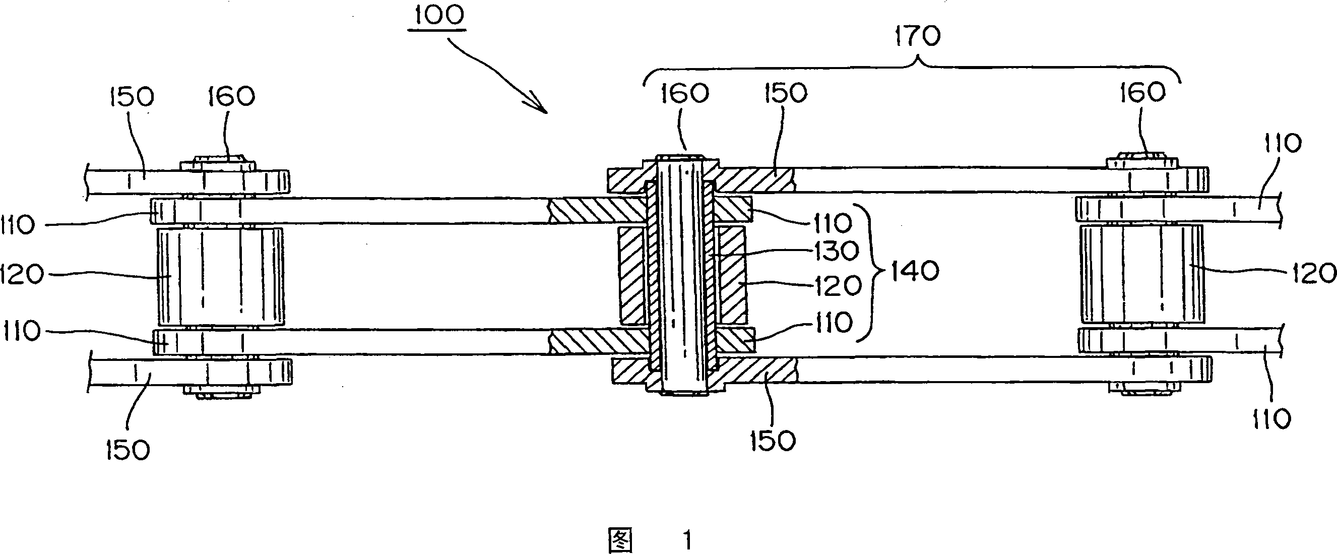
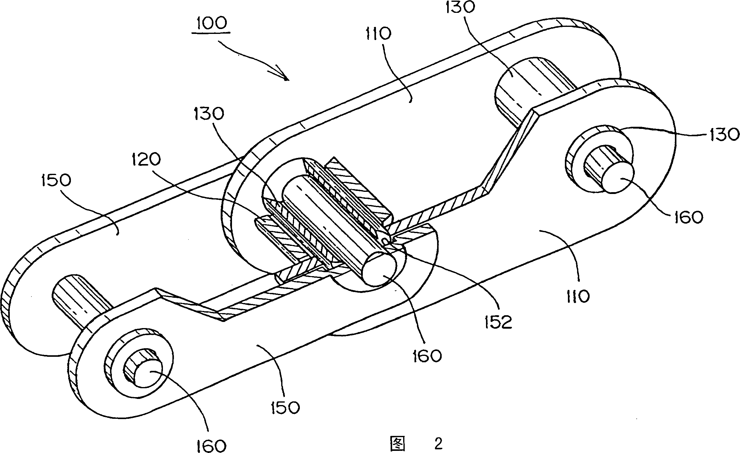
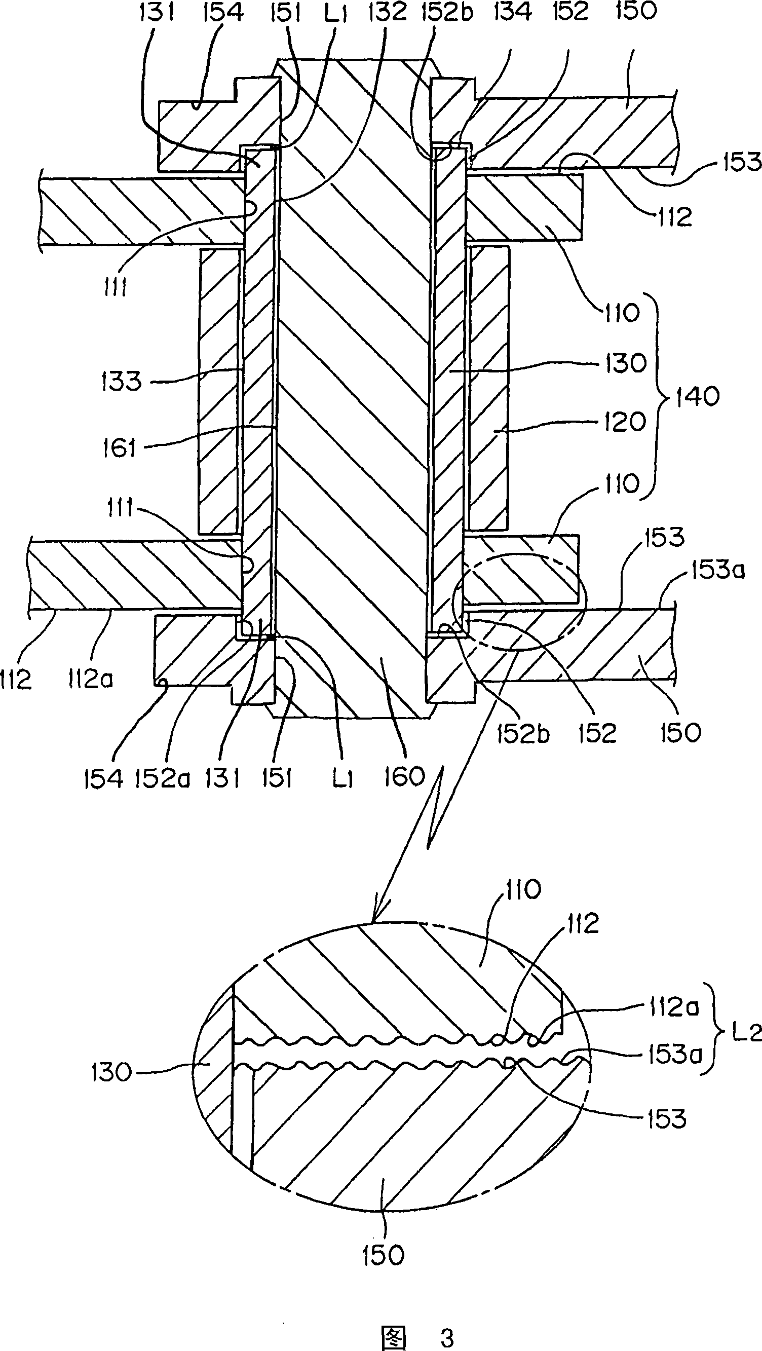
[0042] Here, FIG. 1 is an overall schematic view showing a part of the oil-free chain as a first embodiment of the present invention, FIG. 2 is a perspective view showing a connected state of the oil-free chain shown in FIG. 1 , and FIG. 3 is a The sectional view of the oil-free chain shown in Fig. 1 is enlarged and observed. Fig. 4 is an assembly dimension drawing of the oil-free chain shown in Fig. 1. Fig. 5 shows that the oil-free chain shown in Fig. 1 is moved in the direction of chain travel A dimensional view of a stretched state. FIG. 6 is a dimensional view showing a state in which the oil-free chain of FIG. 1 is deflected in the chain width direction.

[0043] First, as shown in FIGS. 1 and 3 , the oil-free chain 100 according to the first embodiment of the present invention includes a pair of front and rear sleeves 130 , 130 in which bot...


PUM


Abstract

The invention provides an oil-free chain which can prevent the lubricant from leaking and outside dust from entering into, restrain the slide contact abrasion between a connecting pin and a sleeve, prevent the abrasion of the chain from aggravating, and obviously reducing the production load of the chain without increasing the quantity of the chain component. The oil-free chain (100) is characterized in that an inner chain link (140) formed by pressing a sleeve (130) into an inner board (110) is alternately connected with an outer chain link (170) which is formed by pressing the connecting pin (160) passing through the sleeve (130) into an outer board (150) on the length direction of the chain; lubricants are sealed between the sleeve (130) and the connecting pin (160); and a convex end part (131) of the sleeve (130) which is convex from the outer side (112) of the inner board (110) is respectively supported on a circular sleeve axle-bearing support part (152) which is uplifted and formed towards to the outer side (154) from the inner side (153) of the outer board (150) in a state of excursion.

Description

technical field [0001] The present invention relates to a non-lubricating chain used in a transmission roller chain, a conveyor chain, etc., and particularly relates to a sleeve press fitting in which both ends of a pair of front and rear sleeves are press-fitted into a pair of left and right inner plates An inner link formed in a hole, and an outer link formed by press-fitting both ends of the front and rear pair of connecting pins penetrating into the above-mentioned bushing into the pin press-fitting holes of the left and right pair of outer plates. A non-lubricating chain that is alternately connected in the chain length direction and filled with lubricating oil between the inner peripheral surface of the sleeve and the outer peripheral surface of the connecting pin. Background technique [0002] Conventionally, it is known that an outer link having two ends of the outer link plates connected by a pin and an inner link having two inner link plates connected by a bushing ...

Claims


Application Information

Patent Timeline
Patent Type & Authority Applications(China)
IPC IPC(8): F16G13/06B65G17/38B65G19/20
CPCF16G13/06B65G17/38B65G19/20
Inventor 中川贵司石田裕树青木敏彦三木博文
Owner TSUBAKIMOTO CHAIN CO
Why Eureka
Try Eureka