Hoist-transportation machine trajectory space relationship automated detection method

A hoisting and transporting machinery, automated testing technology, applied in the directions of transportation and packaging, measuring devices, instruments, etc., can solve the problems of hidden dangers of measurement safety operation and scattered operators, so as to reduce the number of measurement operators, eliminate hidden dangers of safety accidents, shorten the Measuring the effect of working time

Inactive Publication Date: 2008-07-02
SHANGHAI BAOSTEEL IND TECHNOLOGICAL SERVICE
View PDF0 Cites 9 Cited by
  • Summary
  • Abstract
  • Description
  • Claims
  • Application Information

AI Technical Summary

Problems solved by technology

In addition to the review of the measurement data, the inspection of the calculation results, and the review of the result report, it takes 12 people to spend nearly 8 hours to complete a 300m long track measurement work (data sampling is carried out at intervals of 3 meters)
With the deepening of safety management in enterprises, the safety management of high-altitude operations is further strengthened, requiring high-altitude workers not to be out of the effective protection of seat belts, while traditional driving track measurement is a labor-intensive high-altitude measurement work that requires a lot of investment Manpower and time, especially the span and straightness of the track, must be fastened to the safety belt during the measurement process and step over the high-altitude safety fence to measure separately, which not only disperses the workers, but also causes great hidden dangers to the safe operation of the measurement

Method used


Image

  • Hoist-transportation machine trajectory space relationship automated detection method
  • Hoist-transportation machine trajectory space relationship automated detection method
  • Hoist-transportation machine trajectory space relationship automated detection method

Examples


specific Embodiment approach

[0037] An automatic detection method for the spatial relationship of hoisting and transporting machinery tracks, which includes the following steps,

[0038] Step 1: Set three or more prisms between the tracks as common reference points;

[0039] Step 2, set up a total station on the head end C of a track A, and set up a measuring point prism that can move along the track on the track; the total station needs to turn off its automatic balancing device;

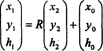
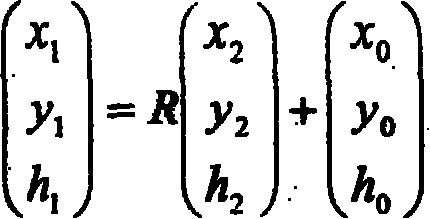
[0040] Step 3, make the measuring point prism move along the track from the head end C to the tail end E, and the total station measures and records the three-dimensional coordinates (x a 、y a ,z a ); At the same time, refer to the relative spatial position relative coordinates of each public reference point record point and the total station;

[0041] Step 4: Set up the total station and the measuring point prism at the head end D of another track B, so that the measuring point prism moves along the track from the head end...


PUM


Abstract

The invention relates to a method for the automatic detection of spatial relationship of orbits in elevating machinery. The method comprises the following steps of: 1) arranging more than three prisms as public reference points between orbits; 2) arranging a total station system at a head end C of an orbit A, arranging a measuring point prism on the orbit in a way that the prism can move along the orbit; 3) allowing the measuring point prism to move from the head end C to a tail end E, tracing and recording the three-dimensional coordinate of the motion track of the measuring point prism on a small rail car by using the total station system, and simultaneously recording the relative coordinates of the relative spatial positions of the points and the total station system, based on each public reference point; 4) repeating the step 3: tracing and recording the three-dimensional coordinate of the motion track of the prism on the small rail car by using the total station system, and simultaneously recording the relative coordinates of the relative spatial positions of the points and the total station system, based on each public reference point as reference; and 5) calculating the linearity and the levelness of each orbit and calculating the span and the height difference of the same sections between two orbits.

Description

technical field [0001] The invention relates to the automatic detection of the rails of gantry-type and bridge-type lifting and transporting machinery, in particular to a detection method for the geometric quantity of the rails. Background technique [0002] With the development of science and technology, industrial production continues to develop in the direction of continuity, scale and automation. Lifting and transporting machinery is widely used in the transportation of raw materials, semi-finished products, and finished products in industrial production, as well as the replacement and maintenance of equipment, and is an important equipment for enterprises. The gantry and bridge crane transport machinery track installed in the industrial plant or on the ground in soft ground, its foundation and surroundings are affected by static load or dynamic load, and uneven settlement or displacement is prone to occur after long-term load operation. The track will be deformed to va...

Claims


Application Information

Patent Timeline
Patent Type & Authority Applications(China)
IPC IPC(8): G01B21/00G01B21/02G01B21/04G01B21/22G01B21/24G01B21/16B66C13/16B66C15/00
Inventor 刘冀平沈彦文杨恩波
Owner SHANGHAI BAOSTEEL IND TECHNOLOGICAL SERVICE
Why Eureka
Try Eureka