
Double-side modulating charge pump circuit and method

A technology of charge pump and circuit, which is applied in the direction of conversion equipment without intermediate conversion to AC, and can solve the problems of voltage conversion efficiency drop and waste of energy, etc.

Inactive Publication Date: 2008-07-02
AIMTRON TECH CORP
View PDF0 Cites 5 Cited by
  • Summary
  • Abstract
  • Description
  • Claims
  • Application Information

AI Technical Summary

Problems solved by technology

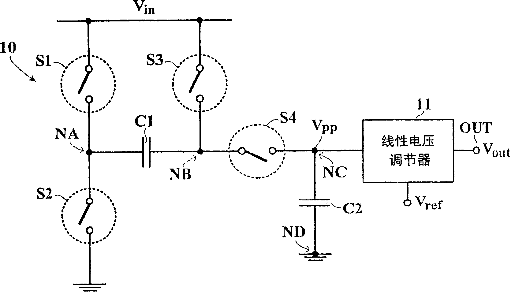
While the linear voltage regulator 11 effectively converts the fixed pump voltage V pp converted into a range between V in with 2*V in adjustable output voltage between V out , but the linear voltage regulator 11 causes a decrease in voltage conversion efficiency and wastes energy

Method used


Image

  • Double-side modulating charge pump circuit and method
  • Double-side modulating charge pump circuit and method
  • Double-side modulating charge pump circuit and method

Examples


Embodiment Construction

[0053] The following description and drawings will make the foregoing and other objects, features, and advantages of the present invention more apparent. Hereinafter, preferred embodiments according to the present invention will be described in detail with reference to the accompanying drawings.

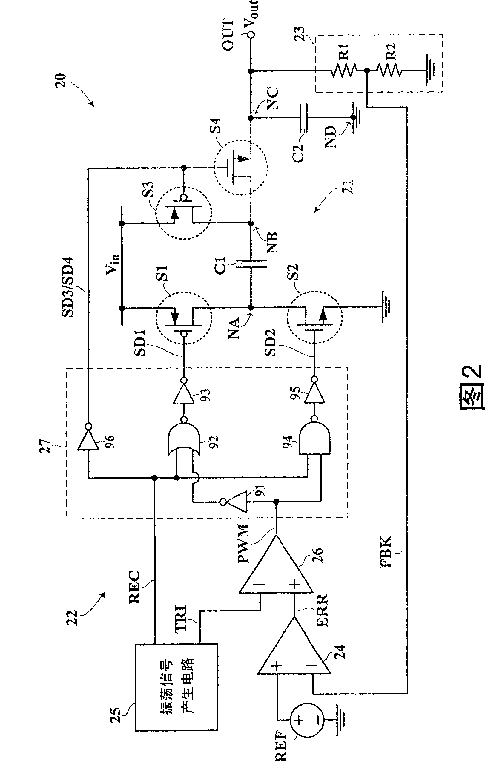
[0054] FIG. 2 shows a detailed circuit diagram of the double-side modulation type charge pump circuit 20 according to the first embodiment of the present invention. 2, the double-sided modulation type charge pump circuit 20 has a charge pump conversion circuit 21 and a double-sided modulation control circuit 22. Under the control of the bilateral modulation control circuit 22, the charge pump conversion circuit 21 effectively reduces the input voltage V in Converted into adjustable output voltage V out , Where the adjustable output voltage V out Polarity and input voltage V in Of the same polarity, and the adjustable output voltage V out The absolute value of is between double V in To twic...


PUM


Abstract

The invention relates to a charge pump circuit of bilateral regulation type which is provided with an output end, a charge pump conversion circuit, and a control circuit of bilateral regulation. The charge pump conversion circuit is provided with a first capacitor, a second capacitor and a switch combinational circuit. The second capacitor is coupled between the output end and a reference potential on the ground. The control circuit of bilateral regulation is used for controlling the switch combinational circuit, so as to allow the charge pump conversion circuit to operate from a first phase to a fourth phase. In the first phase, a first electrode of the first capacitor is in a floating state. In a second phase, the first capacitor is coupled between the reference potential on the ground and input voltage. In a third phase, the first capacitor is coupled between the input voltage and the output end. In the fourth phase, the first electrode of the first capacitor is in a floating state.

Description

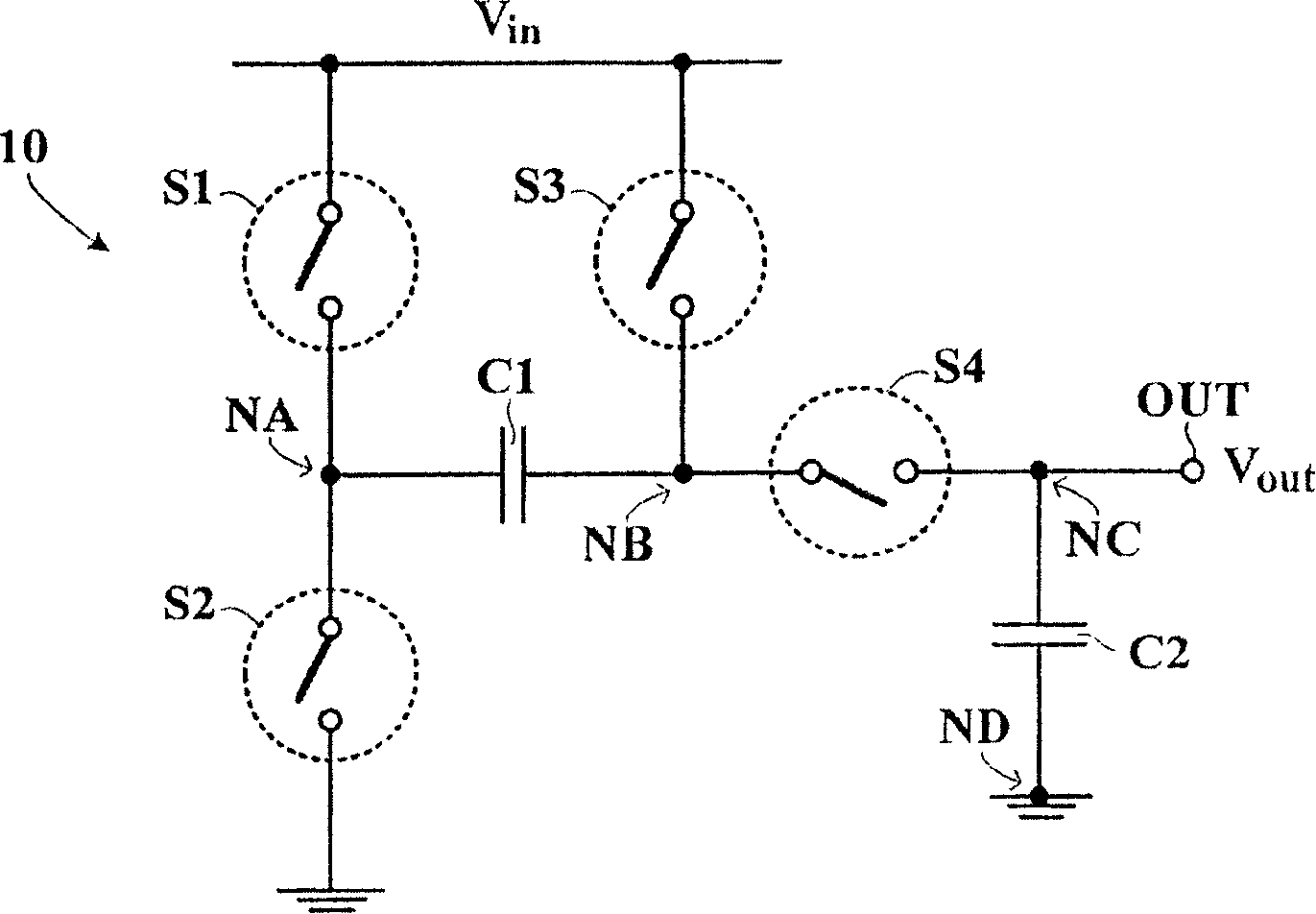
Technical field [0001] The invention relates to a charge pump circuit and a method thereof, in particular to a bilateral modulation type charge pump circuit and a method thereof. Background technique [0002] FIG. 1(a) shows a schematic circuit diagram of a known charge pump circuit 10. 1(a), the known charge pump circuit 10 mainly has a first capacitor C1, a second capacitor C2, and a switch combination circuit. Specifically, the switch combination circuit is composed of a first switch S1, a second switch S2, a third switch S3, and a fourth switch S4. The first switch S1 is coupled to the input voltage V in And the first electrode NA of the first capacitor C1. The second switch S2 is coupled between the first electrode NA of the first capacitor C1 and the ground reference potential. The third switch S3 is coupled to the input voltage V in And the second electrode NB of the first capacitor C1. The fourth switch S4 is coupled between the second electrode NB of the first capacitor ...

Claims


Application Information

Patent Timeline
IPC IPC(8): H02M3/07
Inventor 田雅德
Owner AIMTRON TECH CORP
Learn More