Air outlet nozzle

An air outlet, nozzle technology, used in air handling equipment, heating/cooling equipment, transportation and packaging, etc., can solve problems such as loss, high pressure, etc., and achieve the effect of reducing flow noise

Inactive Publication Date: 2008-07-02
DAIMLER AG
View PDF2 Cites 14 Cited by
  • Summary
  • Abstract
  • Description
  • Claims
  • Application Information

AI Technical Summary

Problems solved by technology

For this purpose, it is known to expand the jet by means of expandable lamellae, but this lamina leads to a large pressure loss

Method used


Image

  • Air outlet nozzle
  • Air outlet nozzle
  • Air outlet nozzle

Examples


Embodiment Construction

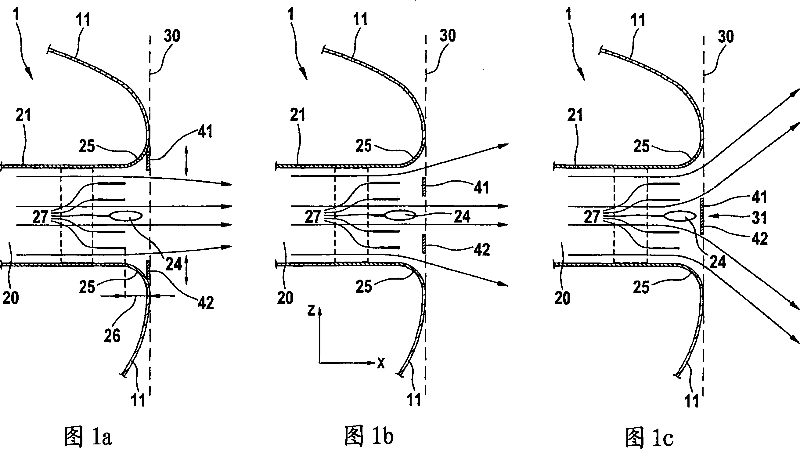
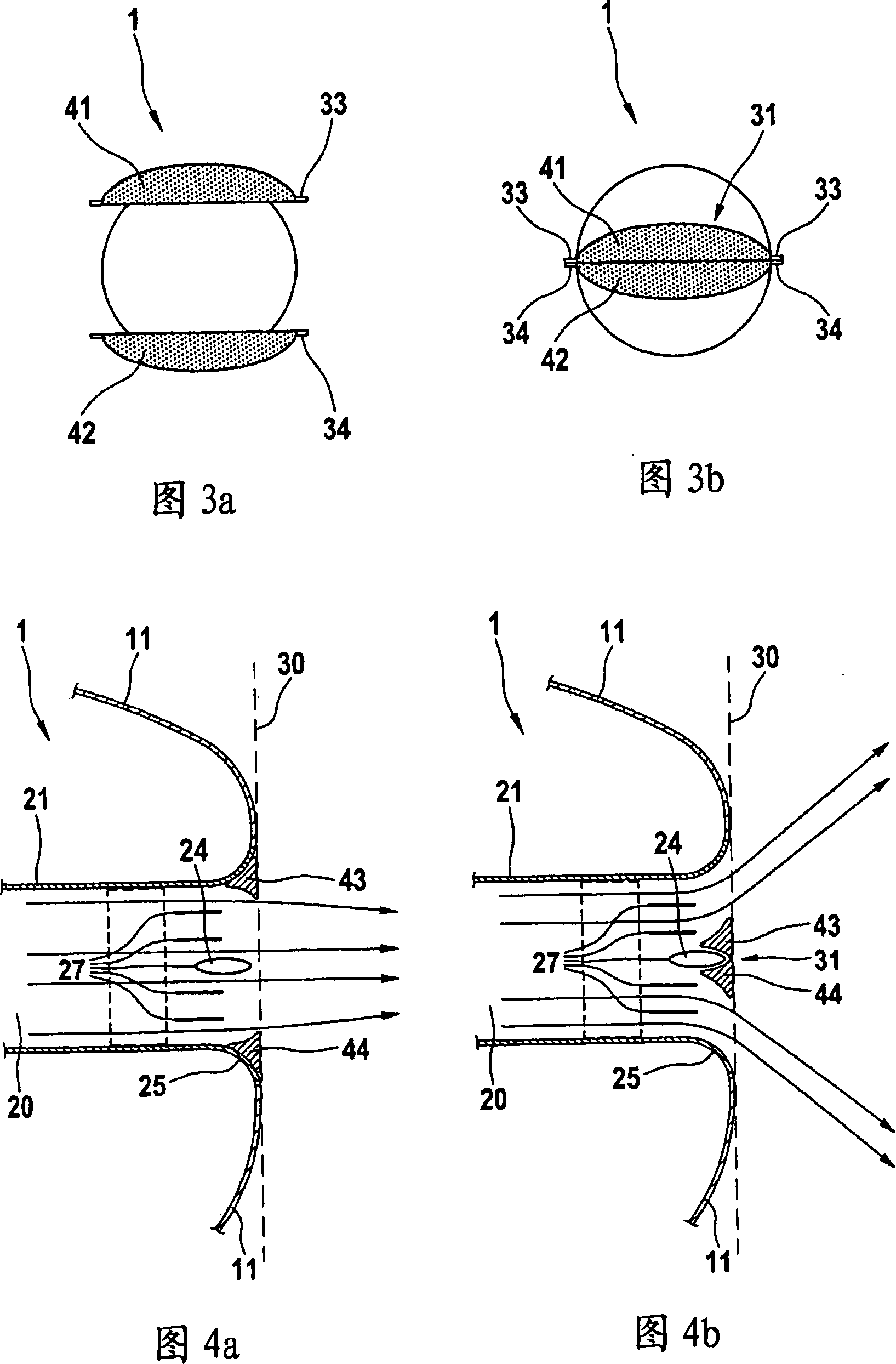
[0033] 1A, 1B and 1C show a schematic sectional view of an air outlet nozzle 1 arranged in a dashboard 11 of a motor vehicle. The air outlet nozzle 1 has an air duct 20 which extends from an air supply device arranged in the center of the vehicle to an air outlet plane 30 distributed on the instrument panel 11 . The air duct 20 conveys air from a central air supply device, preferably a fan of the heating and / or air conditioning system, to one or more air outlet nozzles 1 leading to the vehicle interior.

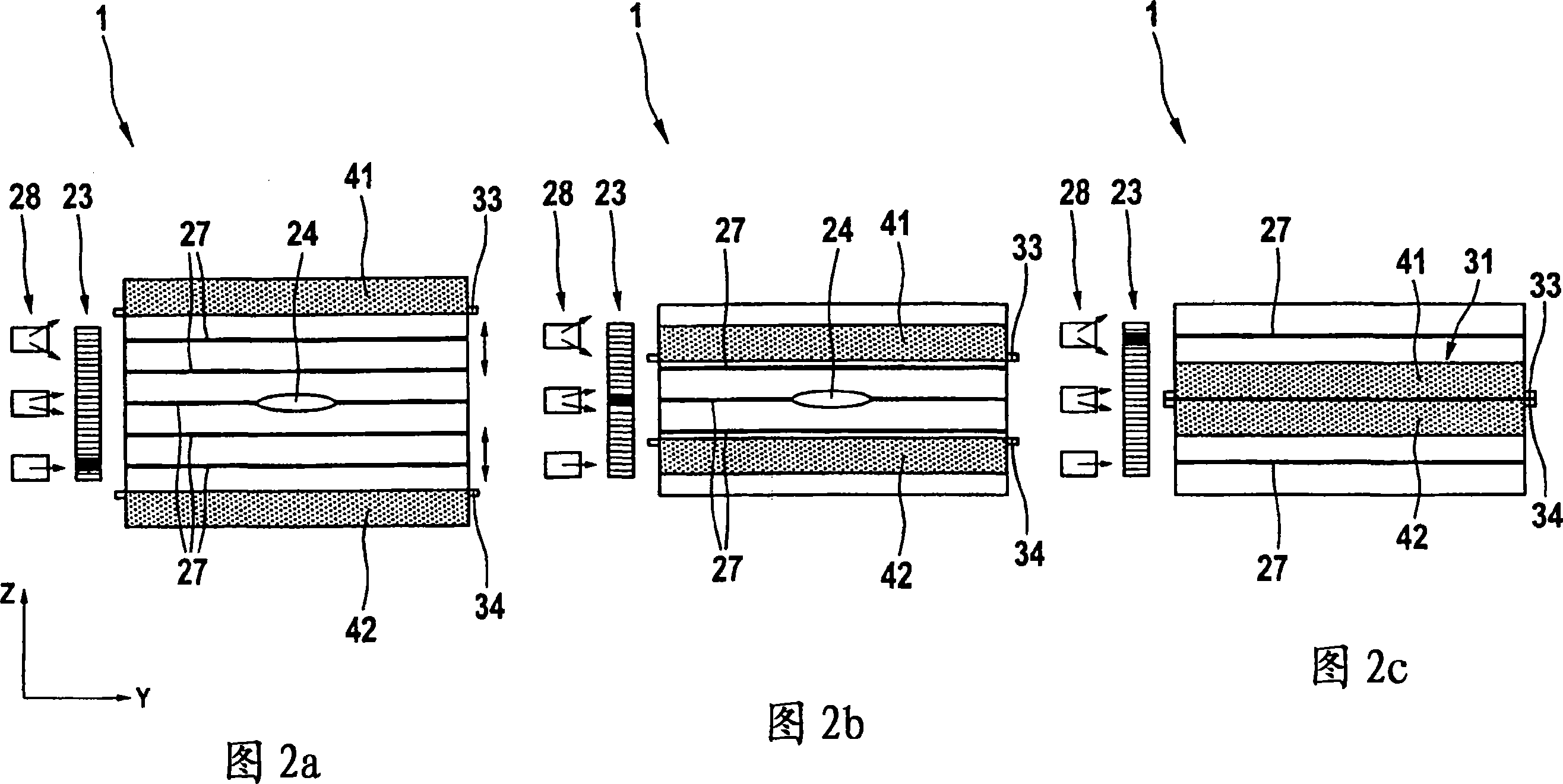
[0034] In the air channel 20 , in the upstream region adjacent to the air outlet plane 30 , a plurality of parallel H-shaped lamellae 27 are arranged, which can pass together through an adjusting element 24 according to their inclination relative to the air channel 20 adjustment in order thereby to control the direction of the air flow coming out of the air outlet nozzle 1 in the horizontal plane. Of course, V-shaped slices can also be used to control the outlet direction in...


PUM


Abstract

The invention relates to an air outlet nozzle which is used to guide air in the passenger compartment of a vehicle. The air outlet nozzle comprises an air channel (20) which leads to an air outlet plane (30), and an impact plate (31) which is arranged on the air outlet plane (31) for beam expansion. The impact plate (31), which is used to adjust a diffuse position on at least two displacably mounted lamellas (29, 41-50), which are arranged in an extended manner in alignment with the air outlet plane, are provided in order to produce an economical air outlet nozzle which provides the best possible beam expansion.

Description

technical field [0001] The invention relates to an air nozzle according to the features of the preamble of claim 1 . Background technique [0002] In air outlet nozzles, in particular for vehicles, it is desirable to be able to generate an air flow which is directed on the one hand and diffused on the other hand. For this purpose, it is known to expand the jet with the aid of expandable lamellas, but these lamellas lead to large pressure losses. Furthermore, it is also known to arrange a straightening body in the air flow, which influences the diffusivity of the air flow due to its pressure distribution. [0003] An air outlet nozzle is known, for example, from GB 624 932 which has a solid deflector plate which can be adjusted relative to the air outlet of an air nozzle by means of a spindle drive. By adjusting this deflector, the pressure situation in the outlet of the air outlet nozzle can be adjusted so that the air flow coming out of the air outlet nozzle is more or le...

Claims


Application Information

Patent Timeline
Patent Type & Authority Applications(China)
IPC IPC(8): B60H1/34
CPCB60H2001/3471B60H1/345
Inventor J・库雷F・弗吕奥夫
Owner DAIMLER AG
Why Eureka
Try Eureka