A pleated diffuser

A diffuser and pleat technology, applied in the field of pleated diffusers, can solve the problems of difficult machining accuracy, high cost, and difficult processing of tubular diffusers, and achieve low manufacturing cost, light weight, and improved thrust-to-weight ratio The effect of the power-to-weight ratio

Active Publication Date: 2018-01-12
INST OF ENGINEERING THERMOPHYSICS - CHINESE ACAD OF SCI
View PDF6 Cites 0 Cited by
  • Summary
  • Abstract
  • Description
  • Claims
  • Application Information

AI Technical Summary

Problems solved by technology

However, the tubular diffuser has problems such as difficult processing, high cost, and difficult to guarantee the processing accuracy. Therefore, there is an urgent need for a new diffuser structure layout that can take into account the aerodynamic performance and processing cost of the diffuser.

Method used


Image

  • A pleated diffuser
  • A pleated diffuser
  • A pleated diffuser

Examples


Embodiment Construction

[0033] In order to make the object, technical solution and advantages of the present invention clearer, the present invention will be described in further detail below in conjunction with specific embodiments and with reference to the accompanying drawings.

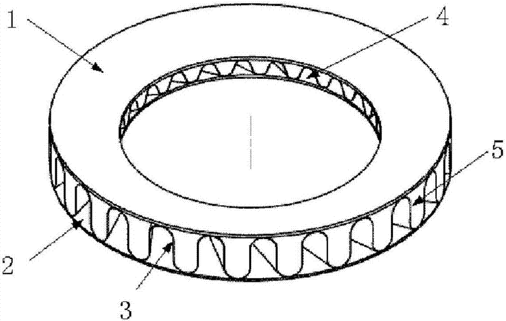
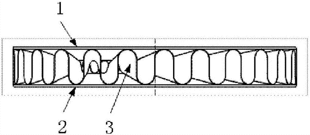
[0034] Such as Figure 1-6 As shown, the pleated diffuser of the embodiment of the present invention includes an upper cover plate 1, a lower cover plate 2 and a pleated structure 3, the pleated structure 3 is in the shape of an annular pleated belt, and the upper cover plate 1 and the lower cover plate 2 are annular Plate-shaped structure, the pleated structure 3 is sandwiched between the upper cover plate and the lower cover plate, and an air flow channel 8 is formed between the upper cover plate, the lower cover plate and the pleated structure, and the flow section of the air flow channel gradually expands along the direction of increasing radius , the pressure increases after the gas flow passes through the gas passag...


PUM


Abstract

The invention provides a fold-shaped pressure expander which comprises an upper cover plate, a lower cover plate and a folded structure. The fold-shaped structure is in an annular fold belt shape, the upper cover plate and the lower cover plate are of annular-plate-shaped structures, the folded structure is clamped between the upper cover plate and the lower cover plate, air flow channels are formed between the upper cover plate, the lower cover plate and the folded structure, the circulation cross sections of the air flow channels are gradually expanded in the increasing direction of radius, and the pressure of air flow is increased after air flow passes through the air flow channels. The fold-shaped pressure expander is large in air flow channel flow area and small in flowing blockage, efficiency of a compressor is improved, and the thrust-weight ratio is raised; the pressure expander is simple and compact in structure, low in weight, convenient to machine and mount and low in cost, and transformation and upgrading of the compressor are facilitated; the ends of wave crests and wave troughs for forming air flow channel air inlets are of specially-shaped structures, and the pressure expansion effect of the fold-shaped pressure expander is enhanced; rectifier channels are turned back to make air flow direction be converted to the direction of an air inlet of a next grade of an air pressing structure.

Description

technical field [0001] The invention relates to the technical field of compressors, in particular to a corrugated diffuser. Background technique [0002] The centrifugal compressor is an important component in most small gas turbines and turboshaft engines, consisting of an impeller and a diffuser. The role of the diffuser is not only to convert the kinetic energy of the centrifugal impeller rotation into the airflow energy into pressure potential energy, but also to twist the high-speed airflow with radial and tangential velocities flowing out of the centrifugal impeller into pure axial airflow as much as possible through the blades. supplied to the combustion chamber for combustion. The performance of the diffuser directly affects the working state of the compressor stage and the combustion chamber, which in turn has a greater impact on the performance of the whole machine, and the flow loss generated by the diffuser accounts for about 30% of the loss of the centrifugal c...

Claims


Application Information

Patent Timeline
Patent Type & Authority Patents(China)
IPC IPC(8): F04D29/44
CPCF04D29/441
Inventor 李钢
Owner INST OF ENGINEERING THERMOPHYSICS - CHINESE ACAD OF SCI
Why Eureka
Try Eureka