Rock debris filtering device

A filtering device and cuttings technology, which is applied in the field of cuttings filtering devices, can solve the problems of low working pressure of the separator, inability to separate specific gravity, etc., and achieve the effects of large internal space, reduction of flushing times, and large flow area.

Inactive Publication Date: 2015-04-15
CHINA PETROCHEMICAL CORP +1
View PDF7 Cites 11 Cited by
  • Summary
  • Abstract
  • Description
  • Claims
  • Application Information

AI Technical Summary

Problems solved by technology

The vibrating screen can only be connected downstream of the throttle valve to remove cuttings in the drilling fluid, which cannot solve the above problems; if the hydrocyclone is installed before the throttle valve for cuttings separation, the problem is that the working pressure of the separator Low, and cannot separate particles with small specific gravity such as rubber

Method used


Image

  • Rock debris filtering device
  • Rock debris filtering device
  • Rock debris filtering device

Examples


Embodiment 1

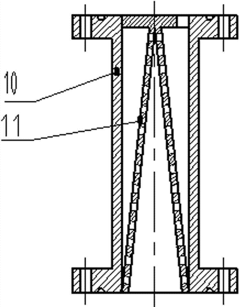
[0017] Embodiment 1, in conjunction with attached figure 1 And attached figure 2 .

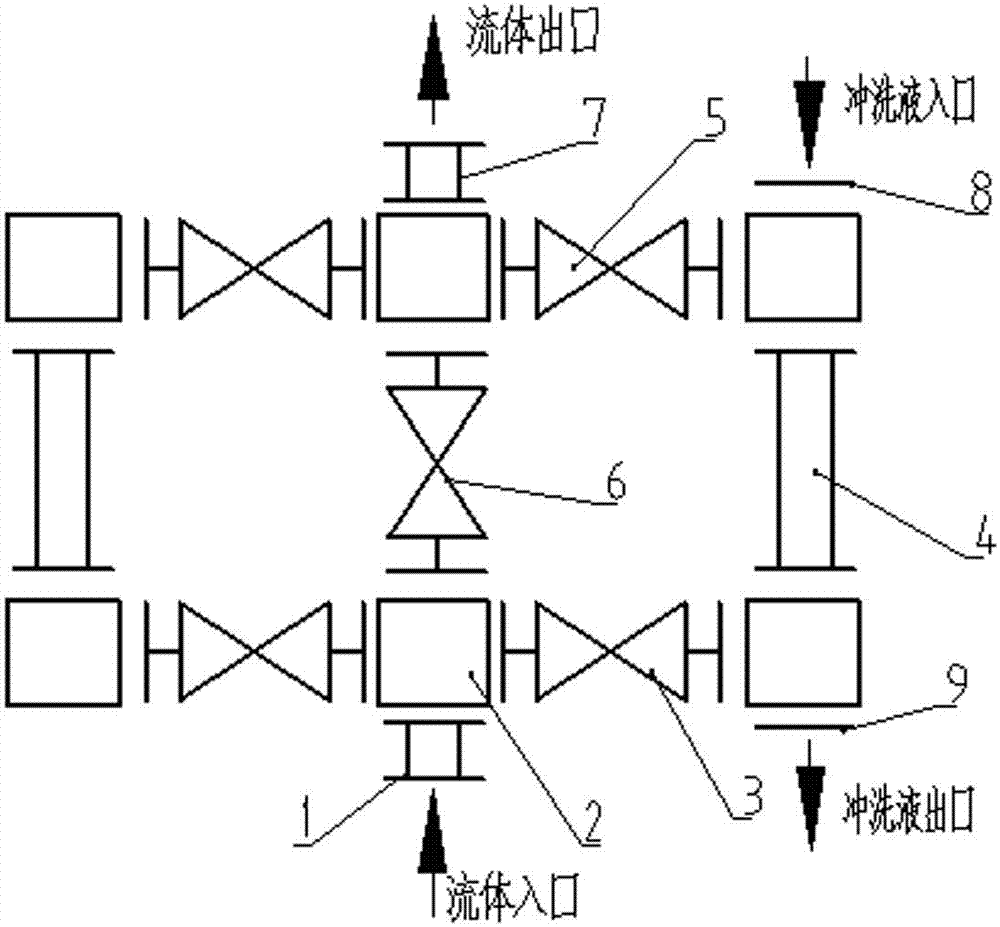
[0018] A cuttings filtering device includes a stop valve, a connecting pipeline and a filter. The inlet pipe 1 of the debris filtering device is connected to the multi-pass block 2, and the downstream of the multi-pass block 2 is sequentially connected to the stop valve A3, the filter 4, the stop valve B5 and the outlet pipe 7 to form a debris filter channel; The downstream of the through block 2 is sequentially connected with the shut-off valve C6 and the outlet pipe 7 to form a non-filtering channel for cuttings; the upstream and downstream of the filter 4 are connected with the flushing pipeline outlet 9 and the flushing pipeline inlet 8 respectively. The downstream of the multi-pass block 2 is connected to a backup filter channel of a cuttings filter channel; the filter 4 on the filter channel and the backup filter channel is composed of an external filter housing 10 and an internal fil...

Embodiment 2

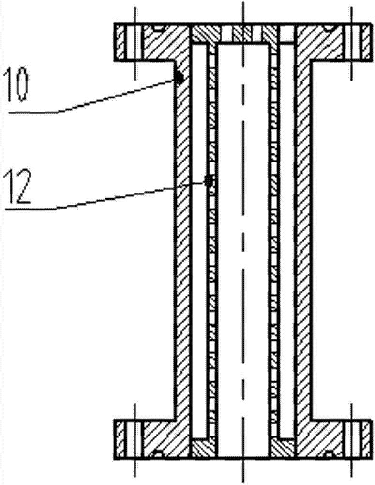
[0019] Embodiment 2, in conjunction with attached figure 1 and 3 .

[0020] A cuttings filtering device includes a stop valve, a connecting pipeline and a filter. The inlet pipe 1 of the debris filtering device is connected to the multi-pass block 2, and the downstream of the multi-pass block 2 is sequentially connected to the stop valve A3, the filter 4, the stop valve B5 and the outlet pipe 7 to form a debris filter channel; The downstream of the through block 2 is sequentially connected with the shut-off valve C6 and the outlet pipe 7 to form a non-filtering channel for cuttings; the upstream and downstream of the filter 4 are connected with the flushing pipeline outlet 9 and the flushing pipeline inlet 8 respectively. The downstream of the multi-pass block 2 is connected to a backup filter channel of a cuttings filter channel; the filter 4 on the filter channel and the backup filter channel is composed of an external filter housing 10 and an internal filter core 12, and ...

Embodiment 3

[0021] Embodiment 3, in conjunction with attached figure 1 And attached Figure 4 .

[0022] A cuttings filtering device includes a stop valve, a connecting pipeline and a filter. The inlet pipe 1 of the debris filtering device is connected to the multi-pass block 2, and the downstream of the multi-pass block 2 is sequentially connected to the stop valve A3, the filter 4, the stop valve B5 and the outlet pipe 7 to form a debris filter channel; The downstream of the through block 2 is sequentially connected with the shut-off valve C6 and the outlet pipe 7 to form a non-filtering channel for cuttings; the upstream and downstream of the filter 4 are connected with the flushing pipeline outlet 9 and the flushing pipeline inlet 8 respectively. The filter 4 of the filtering channel is composed of an external filter housing 10 and an internal filter core 13, and the filter core is processed with through holes; the filter core is in the shape of a truncated cone 13.

[0023] During...


PUM


Abstract

The invention discloses a rock debris filtering device. The rock debris filtering device comprises a stop valve, a connecting pipeline and a filter. The rock debris filtering device is provided with a rock debris filtering channel, a rock debris non-filtering channel and a standby filtering channel; a filter cartridge can be conical, cylindrical or in a round-table shape; an inlet and an outlet of the rock debris filtering device can be respectively installed with a pressure measuring device; and the upstream and the downstream of the filter are connected with an outlet of a flushing pipeline and an inlet of the flushing pipeline. The rock debris filtering device has the advantages of small pressure reduction, strong rock debris filtering capacity, a small number of flushing times for the filter cartridge and on-line cleaning.

Description

technical field [0001] The invention relates to a cuttings filtering device, in particular to a cuttings filtering device for fluid flowing before a throttle valve in the drilling process of oil and gas fields. Background technique [0002] During underbalanced drilling, controlled pressure drilling, and other drilling or downhole operations in oil and gas fields, throttle valves are often required to control the fluid returned from the wellhead to control the back pressure value or the flow rate of the fluid returned from the wellhead within a reasonable range. During the use of conventional choke valves, the fluid returned from the wellhead reaches the choke valve without any screening or filtering. During the operation of the throttle valve, a problem often encountered is that relatively large solid particles can restrict or block the throttle valve, so that the flow control of the throttle valve becomes irregular. The solid particles that cause choke plugging may be cut...

Claims


Application Information

Patent Timeline
Patent Type & Authority Applications(China)
IPC IPC(8): E21B21/01
CPCE21B21/01
Inventor 李作会王树江于海叶陈永明于铁军赵义李晓段光辉朱焕刚
Owner CHINA PETROCHEMICAL CORP
Why Eureka
Try Eureka