Installation head

A technology for installing heads and passages, applied in the direction of electrical components, electrical components, etc., can solve problems such as inconvenience and improve practicability, and achieve the effect of shortening time and improving practicability

Active Publication Date: 2013-04-10
FUJI KK
View PDF7 Cites 11 Cited by
  • Summary
  • Abstract
  • Description
  • Claims
  • Application Information

AI Technical Summary

Problems solved by technology

Therefore, in order to check the contamination of the filter, etc., it is necessary to stop the operation of the mounting head and take out the filter from the inside of the mounting head, which is very

Method used


Image

  • Installation head
  • Installation head
  • Installation head

Examples


Embodiment Construction

[0030] Hereinafter, as a mode for implementing the present invention, embodiments of the present invention will be described in detail with reference to the drawings.

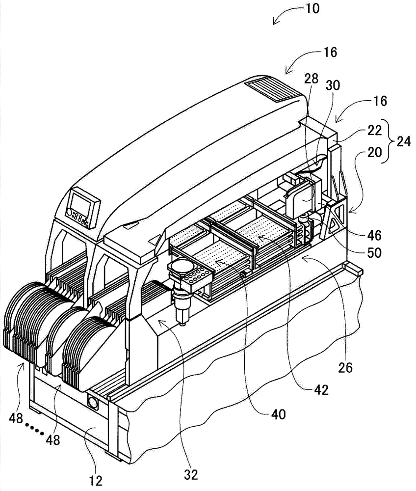
[0031] figure 1 An electronic component mounting device (hereinafter, sometimes simply referred to as a "mounting device") 10 is shown. This figure is a perspective view with part of the exterior components of the mounting device 10 removed. The mounting device 10 includes a system base 12 and two electronic component mounting machines (hereinafter, sometimes simply referred to as "mounting machines") 16 arranged side by side on the system base 12 to mount electronic components on the circuit board. Operation. In addition, in the following description, the direction in which the mounting machines 16 are arranged is called an X-axis direction, and the horizontal direction perpendicular|vertical to this direction is called a Y-axis direction.

[0032] The mounting machine 16 included in the mounting device 10 ...


PUM


Abstract

The invention provides an installation head with high practicality. The installation head is used for absorbing and holding electronic elements so as to install the electronic elements on a circuit substrate. The installation head comprises an absorption passage way (62) connected with a negative pressure source and formed inside the installation head; a filter (64) arranged on the outer periphery of the absorption passage way; an absorption port (68) opened towards the lower end face of the installation head and applied for absorbing and holding electronic elements; and communicators (66, 70, 72) making the absorption port and the absorption passage way communicated. The communicators are opened towards the outer periphery of the installation head so that the filter can be noticed and identified through the opening. By adopting the above-mentioned structure, the outer periphery of the filter with dust attached thereon can be observed and identified from the outside of the installation head. Therefore, the pollution of the filter can be detected without taking the filter out of the installation head. The practicality of the installation head is thus increased.

Description

technical field [0001] The present invention relates to a mounting head for suction-holding an electronic component in order to mount the electronic component on a circuit board. Background technique [0002] Most mounting heads have a structure that has a suction passage connected to a negative pressure source, and a suction port that is open to the downward end face and connected to the suction passage, and the suction port uses negative pressure to adsorb and hold electronic components. In some mounting heads with such a structure, a filter is provided in the suction passage to prevent dust from being sucked into the mounting head when electronic components are sucked. However, since the diameter of the suction passage is relatively small, when the filter is arranged to cover the end surface of the suction passage, the flow path area of ​​the air passing through the filter is small. Therefore, less air is drawn and the attraction force may be lower. Therefore, in the mo...

Claims


Application Information

Patent Timeline
IPC IPC(8): H05K13/04
Inventor 冈田健人林哲生
Owner FUJI KK
Why Eureka
Try Eureka