Centrifugal Fan with Integrated Thermal Transfer Unit

a technology of centrifugal fans and thermal transfer units, which is applied in the direction of electrical apparatus casings/cabinets/drawers, instruments, and semiconductor/solid-state device details, etc., can solve the problems and reducing airflow resistance. , the effect of reducing or eliminating resistance due to turning

Active Publication Date: 2015-04-30
MICROSOFT TECH LICENSING LLC
View PDF7 Cites 12 Cited by
  • Summary
  • Abstract
  • Description
  • Claims
  • Application Information

AI Technical Summary

Benefits of technology

[0004]Embodiments include a centrifugal fan unit having an integrated thermal transfer unit. Embodiments include one or more thermal transfer units that at least partially surround the fan. Airflow from the fan is at least partially unimpeded between the fan and the thermal

Problems solved by technology

Airflow from the fan is at least partially unimpeded between the fan and the thermal transfer unit, thereby reducing or eliminating the resistance due to turning of the air as in

Method used


Image

  • Centrifugal Fan with Integrated Thermal Transfer Unit
  • Centrifugal Fan with Integrated Thermal Transfer Unit
  • Centrifugal Fan with Integrated Thermal Transfer Unit

Examples


Embodiment Construction

[0015]Overview

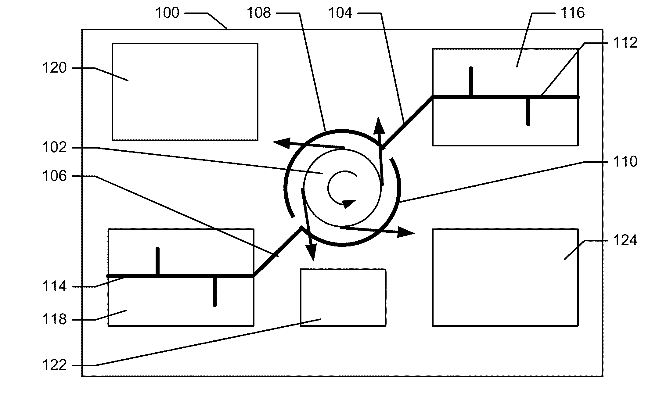
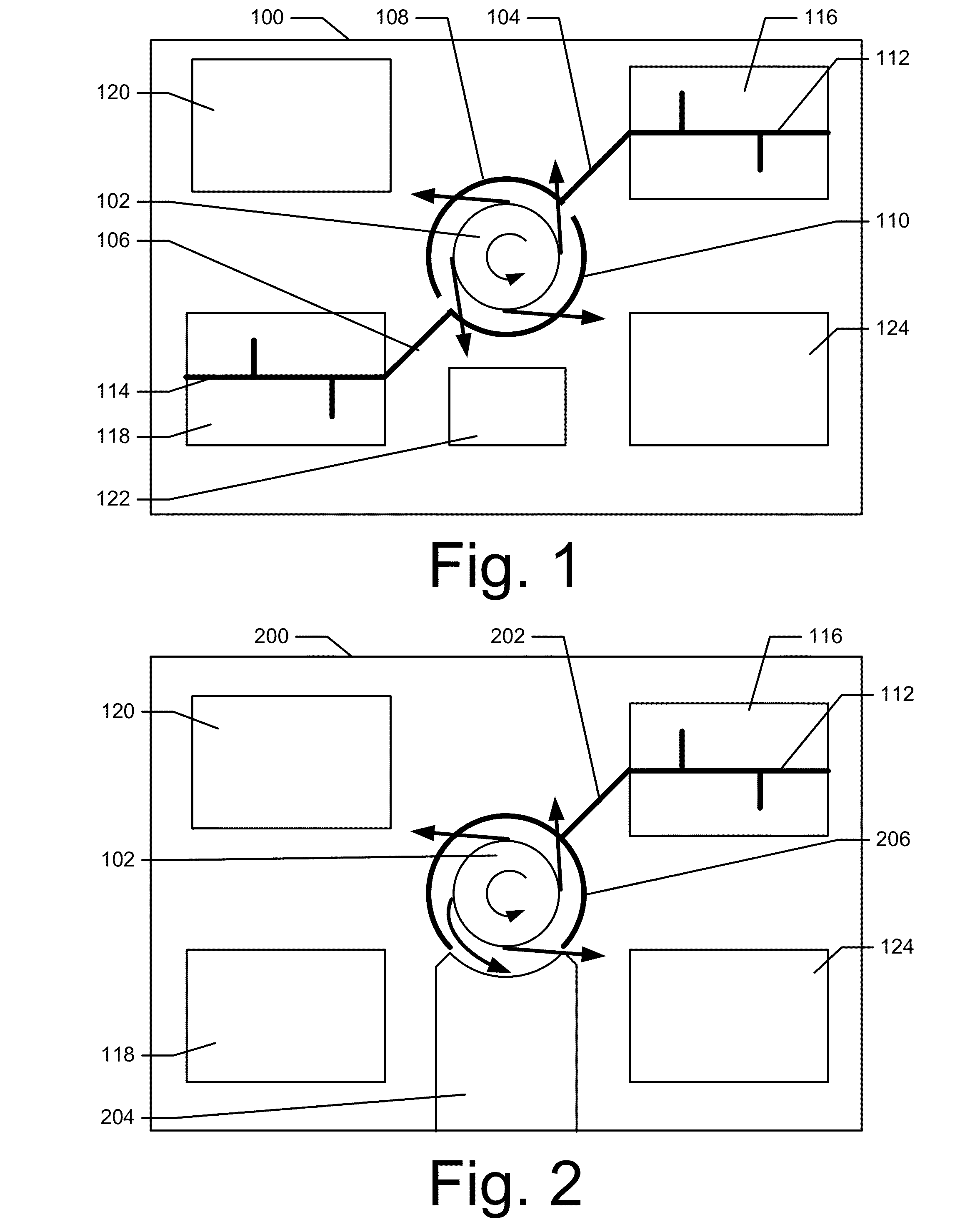
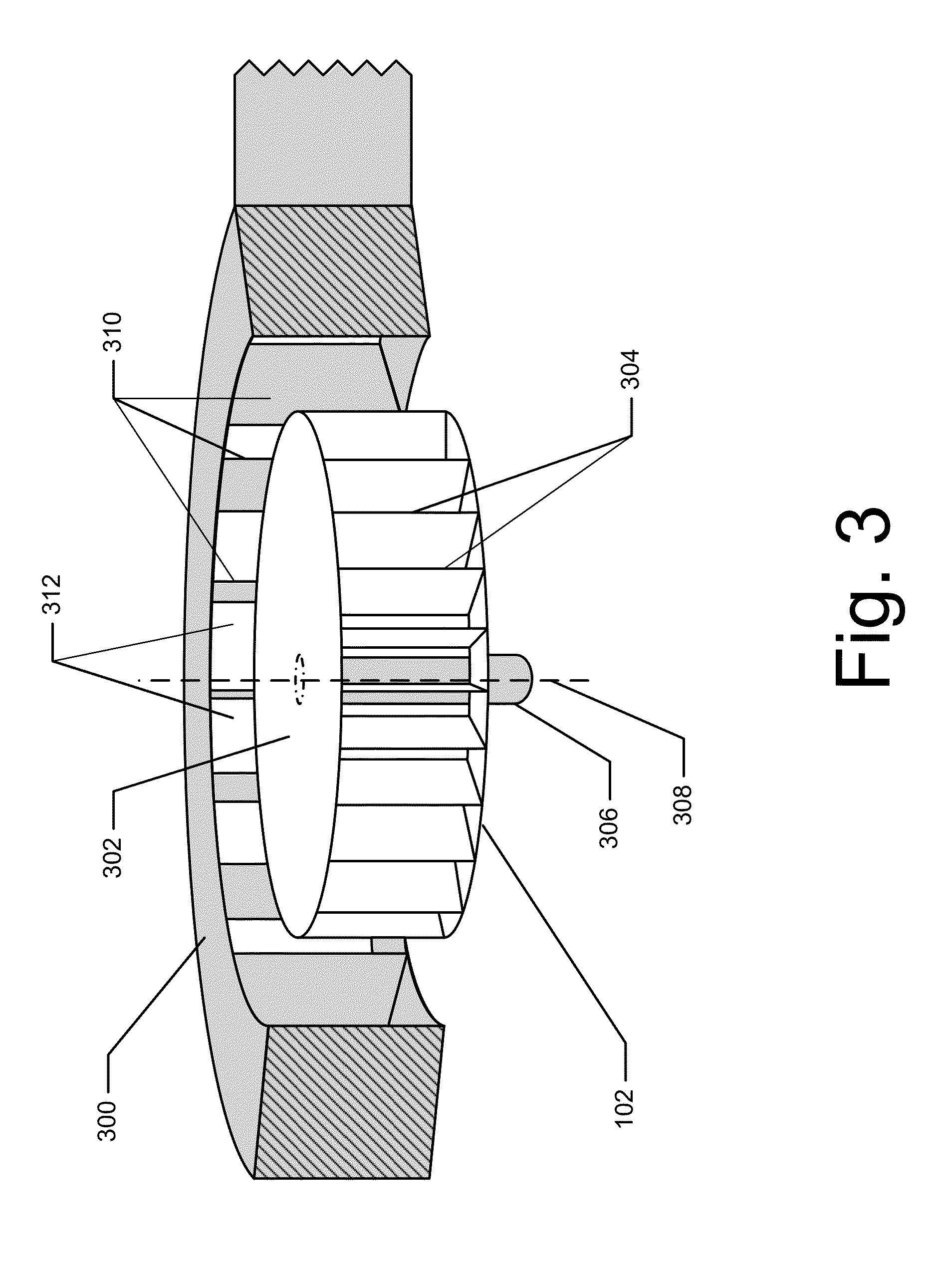
[0016]Embodiments include a centrifugal fan unit having an integrated thermal transfer unit. As noted above, conventional centrifugal fan cooling systems used in computing systems incur losses due to resistance. Embodiments of the present disclosure reduce or eliminate resistance common in conventional fan-based cooling systems. Embodiments include thermal transfer units that at least partially surround the fan. Airflow from the fan is at least partially unimpeded between the fan and the thermal transfer unit, thereby reducing or eliminating the resistance due to turning of the air as in conventional fans. Also, allowing air to blow directly outwards from the fan to the thermal transfer unit, without first directing the air to a relatively narrow outlet, results in a larger cross-sectional flow area and therefore lower airflow resistance. Fans according to embodiments of the present disclosure are system-level fans designed specifically for the computing system into wh...


PUM


Abstract

Disclosed herein are computing devices, and methods of manufacturing computing devices, that have a cooling fan and integrated thermal transfer unit. A centrifugal fan unit includes a rotatable hub, a plurality of blades disposed on the rotatable hub, and a motor coupled to the rotatable hub. The motor causes the rotatable hub to rotate about an axis such that airflow proceeds outward from the centrifugal fan unit along trajectories that are perpendicular to the axis. One or more thermal transfer units have first portions that are coupled to the one or more heat sources and second portions that collectively at least partially surround the centrifugal fan unit.

Description

BACKGROUND[0001]A computing device includes various electronic components that produce heat during operation, such as central processing units, graphical processing units, and so forth. Since such devices can be damaged by overheating, the computing device may include a cooling mechanism. One such mechanism includes a centrifugal fan, which produces airflow in 360 degrees along trajectories that are perpendicular to its axis of rotation. In a conventional arrangement, the centrifugal fan is placed into a housing that directs (“turns”) the airflow towards an outlet. A thermal transfer device includes fins that are situated near the outlet of the centrifugal fan housing. Heat is communicated from the electronic components to the fins by conduction and / or phase change convection (heatpipe), and air blowing from the outlet cools the fins.[0002]Such conventional systems incur losses, such as from resistance due to turning the air towards the outlet. Also, air naturally exits off the impe...

Claims


Application Information

Patent Timeline
IPC IPC(8): G06F1/20
CPCG06F1/20G06F1/203H01L23/467H01L23/433F04D17/16F04D29/582H01L2924/0002F28D15/0275H01L2924/00
Inventor DELANO, ANDREW D.STELLMAN, TAYLORHILL, ANDREW W.
Owner MICROSOFT TECH LICENSING LLC
Why Eureka
Try Eureka