Fluid pressure circuit

A fluid pressure and circuit technology, which is applied to fluid pressure actuators, servo meter circuits, servo motors, etc., can solve the problems of not being able to improve linkage, and achieve the effect of improving linkage

Inactive Publication Date: 2008-07-02
CATEPILLAR SARL
View PDF1 Cites 14 Cited by
  • Summary
  • Abstract
  • Description
  • Claims
  • Application Information

AI Technical Summary

Problems solved by technology

[0017] In short, when the boom cylinder 4bm is linked with the tool actuator 6at, as shown in Figure 12 and Figure 13 As shown, the driving pump 12 can be allocated to the boom cylinder 4bm, and the idle pump 13 can

Method used


Image

  • Fluid pressure circuit
  • Fluid pressure circuit
  • Fluid pressure circuit

Examples


Embodiment Construction

[0044] Referring to the first embodiment shown in FIGS. 1 to 7 , the second embodiment shown in FIG. 8 , and Figure 9 The work machine A shown illustrates the invention in detail.

[0045] Since it has been detailed Figure 9 The working machine A shown is omitted here. The boom 4 of the working device 3 of the working machine A is moved by the boom cylinder 4bm as the first actuator, and the arm 5 connected to the front end of the boom is moved by the boom cylinder 4bm as the first actuator. The arm cylinder 5st of the second actuator is operated, and the attachment 6 connected to the tip of the arm 5 is operated by the tool actuator 6at as a specific actuator.

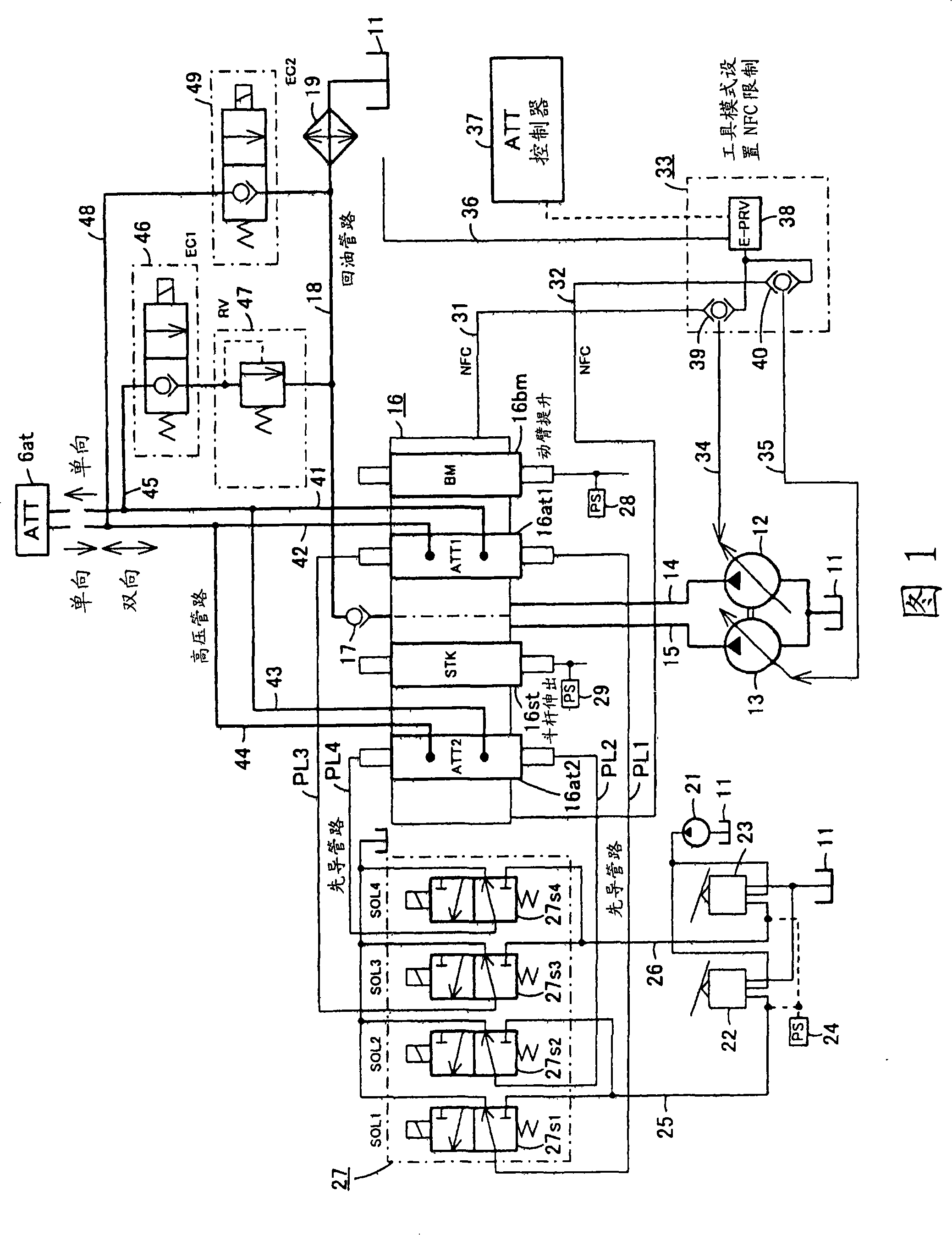
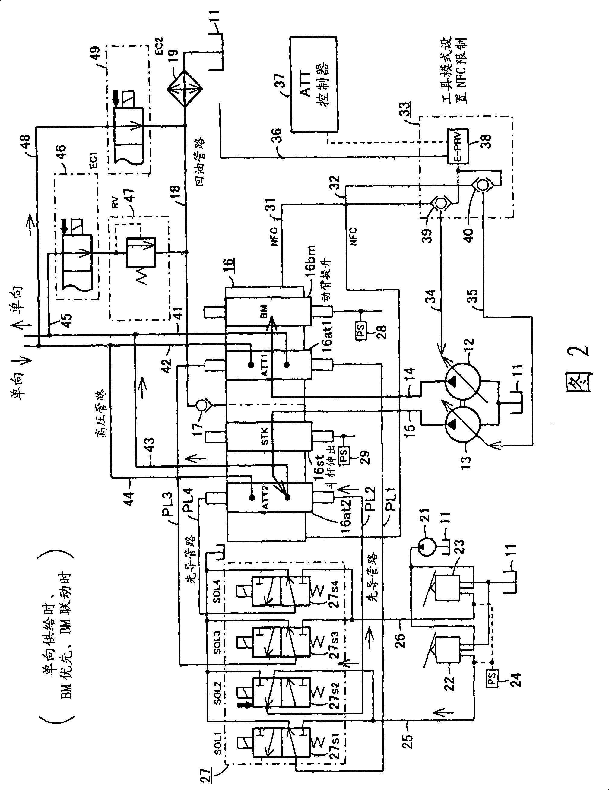
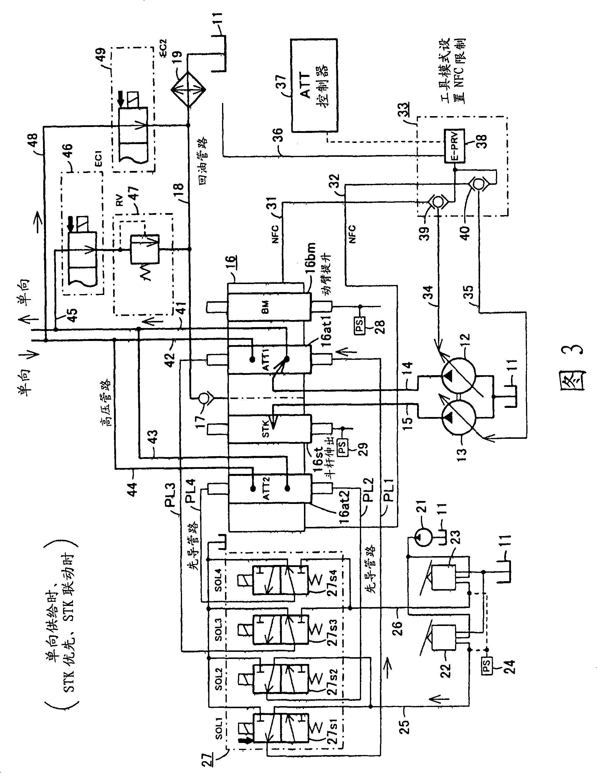
[0046] Fig. 1 shows the first embodiment of the fluid pressure circuit, the suction port of the driving pump 12 as the first pump and the suction port of the idle pump 13 as the second pump are respectively connected on the oil tank 11 containing the working fluid (ie working oil). The drive pump 12 is directly driv...


PUM


Abstract

The present invention provides a fluid pressure circuit in which any one of a first actuator that receives a supply of working fluid from a first pump and a second actuator that receives a supply of working fluid from a second pump operates , both the first pump and the second pump can supply the working fluid to the specific actuator, and the linkage with the specific actuator can be improved. The control valve (16) includes a first set of spool valves receiving a supply of working fluid from the drive pump (12) and a second set of spool valves receiving a supply of working fluid from the idle pump (13). The electromagnetic switching valve device (27) switches the pilot line of the tool control spool valve (16at2) of the second group to the communication state when the first pressure switch (28) detects the action of the spool valve, and the second pressure switch (29) Switch the pilot line of the tool control spool valve (16at1) of the first group to the communication state when performing the spool valve operation detection.

Description

technical field [0001] The present invention relates to a fluid pressure circuit that provides working fluid from a plurality of pumps to a plurality of actuators through a plurality of spool valves. Background technique [0002] The hydraulic circuit of the work machine has the following: operating the electromagnetic switching valve of the selection unit, controlling the control valve for the tool of the work machine, the first converging valve and the second converging valve, selecting the flow rate of the first pump, the first pump and the second converging valve. The combined flow rate of the second pump or the combined flow rate of the first pump, the second pump, and the third pump is supplied to the hydraulic oil supply port leading to the attachment, so that the hydraulic circuit of the working machine can be connected with various attachments. Corresponding to the required flow rate (for example, refer to Patent Document 1). [0003] Such as Figure 9 As shown, th...

Claims


Application Information

Patent Timeline
IPC IPC(8): F15B11/02E02F9/22F15B11/17
CPCE02F9/2228E02F9/2235E02F9/2242E02F9/2285E02F9/2292E02F9/2296F15B11/055F15B11/16F15B11/17F15B2211/20546F15B2211/20576F15B2211/329F15B2211/40515F15B2211/45F15B2211/6313F15B2211/6355F15B2211/7142F15B2211/78Y10T137/86614Y10T137/87209
Inventor 西川裕康岛原圣
Owner CATEPILLAR SARL
Why Eureka
Try Eureka