Tibia endoprosthesis

A tibial and prosthesis technology, applied in the field of knee joint prosthesis, can solve the problem of not limiting the rearward displacement distance of the tibial pad, limiting the front-to-back translation distance of the tibial pad, and failing to ensure that the anterior side of the tibial pad is not lifted, etc. problems, to speed up the recovery time, ensure the stability of movement, and avoid the effect of dislocation

Inactive Publication Date: 2008-07-09
SICHUAN UNIV
View PDF3 Cites 4 Cited by
  • Summary
  • Abstract
  • Description
  • Claims
  • Application Information

AI Technical Summary

Problems solved by technology

In U.S. Patent No. 5,935,173, the posterior part of the tibial liner is lengthened, so that the front side of the tibial liner is not lifted when the knee joint is deeply flexed, effectively preventing dislocation of the knee prosthesis, but this patent does not limit the tibial liner to the tibial Front and rear translation distance on the support
In US Patent No. 6,797,005, the stop pin is designed to limit the anteroposterior translation distance of the tibia

Method used


Image

  • Tibia endoprosthesis

Examples


Embodiment Construction

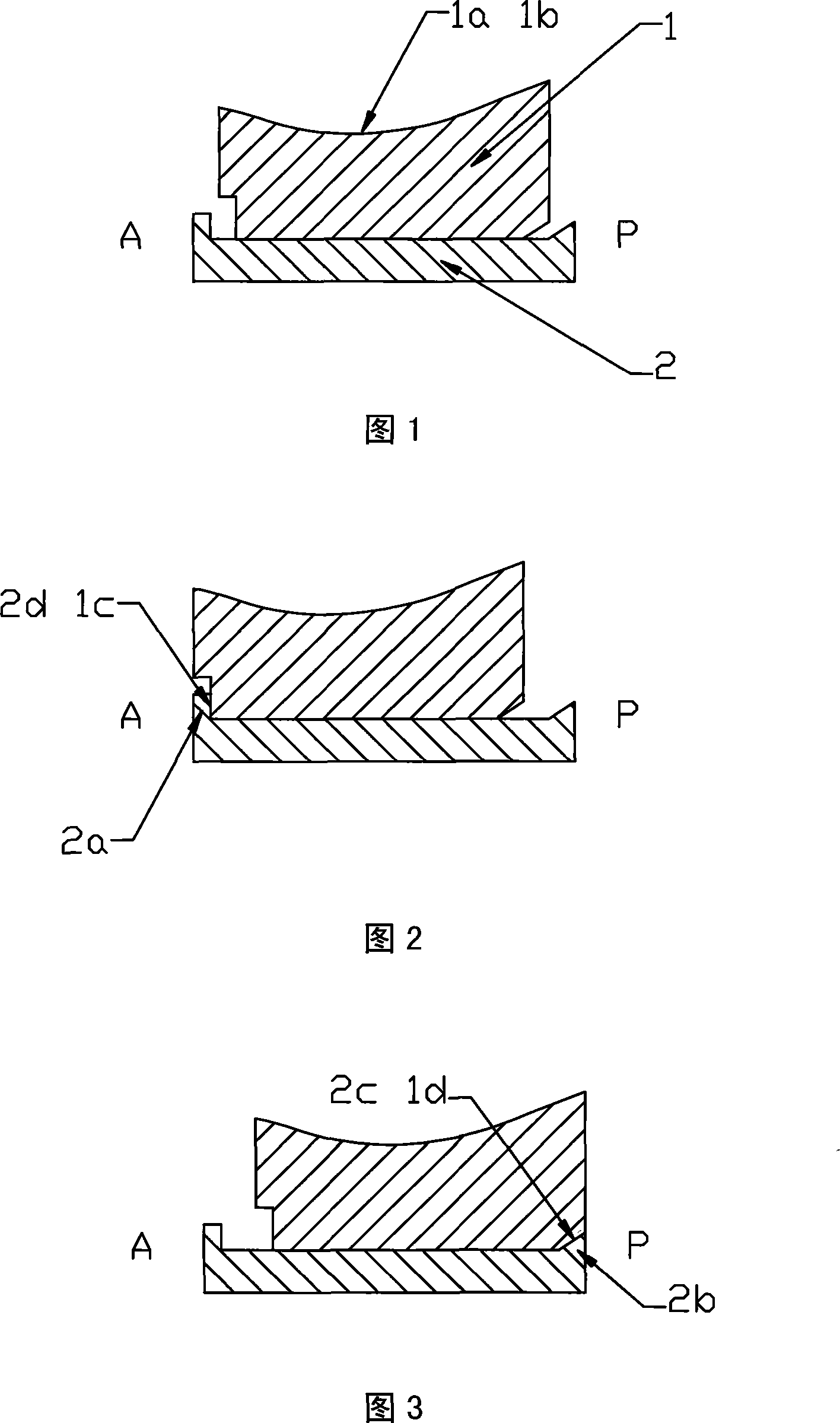
[0019] In Figure 1, Figure 2 and Figure 3, the tibial abutment 2 is connected to the proximal end of the tibia through the tibial mounting stem (not shown in the figure) or bone cement, and the tibial liner 1 is placed on the femoral prosthesis (not shown in the figure) Between the tibial bearing 2 and the tibial bearing 2, the tibial liner 1 can translate along the A-P direction (anterior-posterior direction) on the tibial bearing 2. Simulate the normal human natural knee joint movement process.

[0020] In FIG. 1 , the knee joint is in a fully extended knee position. At this time, the tibial pad 1 is in a free state along the A-P direction (anterior-posterior direction) on the tibial bearing 2 .

[0021] In Fig. 2, the knee joint is in a hyperextended position. At this time, the front positioning surface 1c of the tibial pad 1 is in contact with the inner surface 2d of the front positioning block 2a on the tibial bearing 2, so as to ensure that the forward movement distance ...


PUM


Abstract

The present invention provides a tibial prosthesis which comprises a tibial gasket which moves flat along the forward and the backward directions at a tibial support and the tibial support which is connected with a close end of the tibia. When a knee joint is at the complete knee extension position, the tibial gasket is under the free state along the forward and the backward directions at the tibial support. When the knee joint is over extended, the front positioning face of the tibial gasket is contacted with the inner surface of a front positioning block at the tibial support, so as to ensure that the tibial gasket forward movement distance is limited to avoid damaging the front soft tissue of the knee joint. When the knee joint is at the deep bending knee position, the back oblique positioning face of the tibial gasket is contacted with an incline at a back positioning block at the tibial support, so as to ensure that the tibial gasket backward movement distance is limited to avoid damaging the back tissue of the knee joint. At the same time, the back oblique positioning face of the tibial gasket is matched with the incline at the back positioning block at the tibial support, so as to prevent athe knee prosthesis dislocation caused by lifting the tibial gasket during the deep bending knee position of the knee joint.

Description

technical field [0001] The invention relates to a knee joint internal prosthesis, in particular to a tibial prosthesis applied to a human body. Background technique [0002] The so-called internal prosthesis of the knee joint includes two parts: the femoral prosthesis and the tibial prosthesis. Among them, the femoral prosthesis is connected to the distal end of the femur through a femoral mounting stem or screws, and has inner and outer condyles. The tibial prosthesis is divided into two parts, the tibial bearing and the tibial bearing. The tibial bearing is fixed at the proximal end of the tibia. The tibial lining is located between the femoral prosthesis and the tibial bearing. The articular surfaces of the condyles are matched with the articular surfaces of the inner and outer condyles of the femoral prosthesis to simulate the normal human natural knee joint movement process. [0003] For the human natural knee joint, due to the joint action of the surrounding soft tis...

Claims


Application Information

Patent Timeline
IPC IPC(8): A61F2/38
Inventor 张国亮裴福兴姚进沈彬周宗科
Owner SICHUAN UNIV
Why Eureka
Try Eureka