Engine air valve controlling mechanism

A technology of engine valves and control mechanisms, which is applied in the direction of engine components, machines/engines, mechanical equipment, etc., can solve the problems of many parts, complex structures, complex mechanisms, etc., to improve fuel economy and power, reduce mechanical Loss, optimize the effect of gas distribution

Inactive Publication Date: 2008-07-09
CHERY AUTOMOBILE CO LTD
View PDF0 Cites 12 Cited by
  • Summary
  • Abstract
  • Description
  • Claims
  • Application Information

AI Technical Summary

Problems solved by technology

[0003] However, these traditional engine valve trains have many components and relatively complex mechanisms, resulting in a high failure rate
Although the valve timing of the engine can be adjusted to optimize the intake and exhaust through the variable valve timing mechanism, the valve lift of the engine cannot be changed.
To change the valve lift of the engine, it is necessary to change the profile of the cam, etc., and the structure is more complicated.

Method used


Image

  • Engine air valve controlling mechanism

Examples


Embodiment Construction

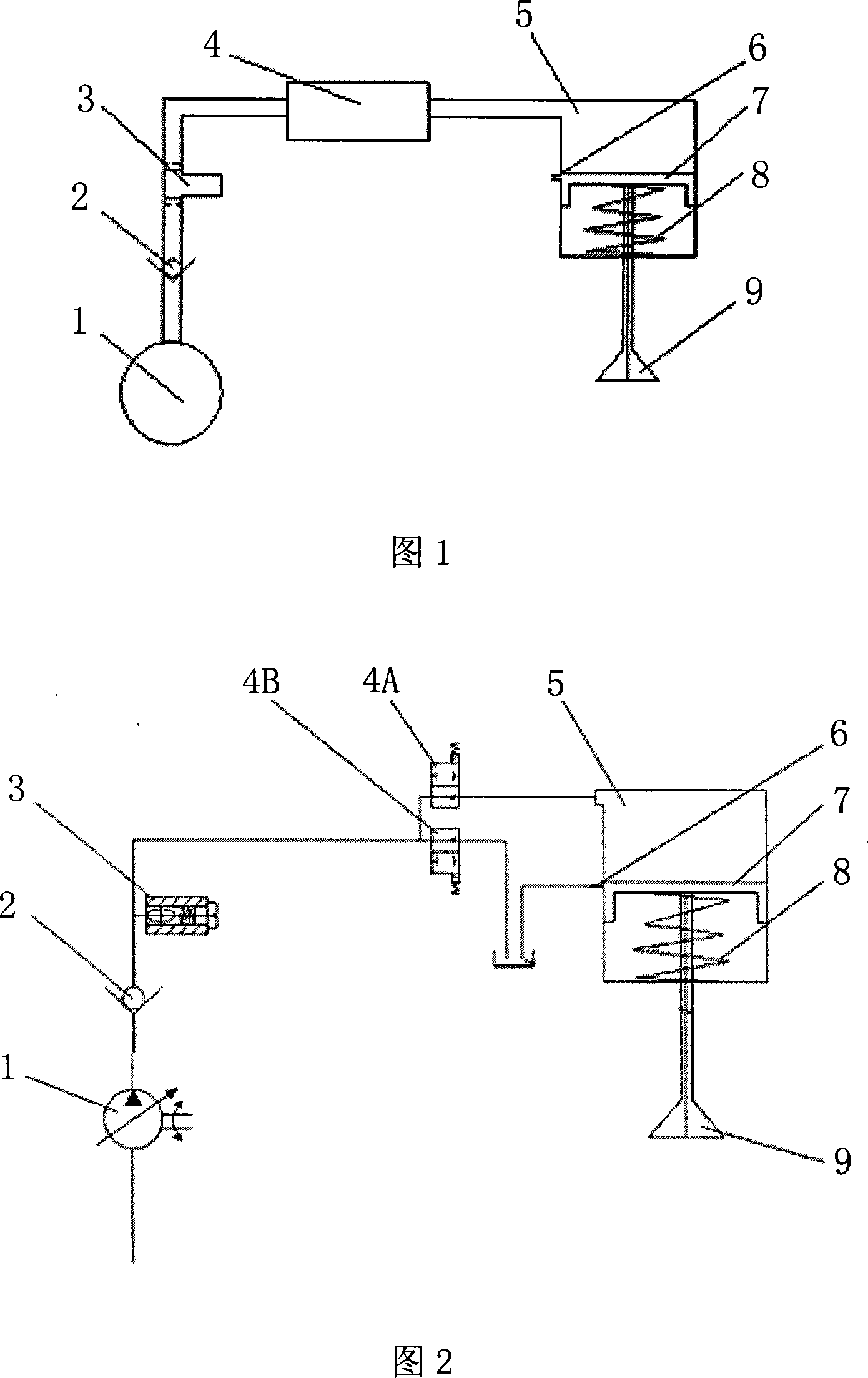
[0009] As shown in Fig. 1, 2, a kind of engine valve control mechanism, the present invention comprises the oil pump 1 that is driven by engine crankshaft, and the oil outlet end of oil pump 1 is provided with check valve 2, and the oil outlet end of check valve 2 and electromagnetic valve Or the oil inlet end of the electromagnetic valve group 4 is connected, and the oil outlet end of the electromagnetic valve or the electromagnetic valve group 4 is connected with the control device for controlling the valve lift and the oil tank respectively.

[0010] Since the engine speed has an influence on the speed of the oil pump, the pump oil volume is large when the speed is high, and the pump oil volume is small when the speed is low. The present invention utilizes this relationship to drive and control the oil pumped by the oil pump through the solenoid valve or solenoid valve group 4 Valve lift control device, this control device cooperates with the opening and closing of the solen...


PUM


Abstract

The invention relates to the engine distribution field, in particular to an engine valve control mechanism. The invention comprises an oil pump (1) driven by an engine crankshaft. The oil outlet end of the oil pump (1) is provided with a one-way valve (2). The oil outlet end of the one-way valve (2) is connected with the oil inlet end of an electromagnetic valve or an electromagnetic valve group (4). The oil outlet end of the electromagnetic valve or the electromagnetic valve group (4) is connected with a control device to control the lift range of an engine valve and a tank, respectively. As the invention cancels a cam mechanism and a timing transmission system in the traditional engine valve mechanism, the structure of the invention is simple; mechanical loss is reduced; gas distribution is optimized; desirable valve timing and valve lift range are achieved; economical efficiency and dynamic property of fuel of the engine are improved.

Description

technical field [0001] The invention relates to the field of engine gas distribution, in particular to an engine valve control mechanism. Background technique [0002] Most of the existing engine valve trains are made up of camshafts, rocking arms, hydraulic tappets and other mechanisms. During the working process, the crankshaft drives the camshaft through a belt or a chain to realize the intake and exhaust of the engine. If a variable valve timing mechanism is installed, the intake and exhaust of the engine can also be optimized through the variable valve timing mechanism, thereby improving the fuel economy and power of the engine. [0003] However, these traditional engine valve trains have many parts and relatively complex mechanisms, which lead to a high failure rate. Although the valve timing of the engine can be adjusted to optimize the intake and exhaust through the variable valve timing mechanism, the valve lift of the engine cannot be changed. To change the valv...

Claims


Application Information

Patent Timeline
Patent Type & Authority Applications(China)
IPC IPC(8): F01L9/02F01L1/34F01L9/10F01L9/40
Inventor 赵辉张士鹏芦清兆王孟轲黄前海汤绪雯张华
Owner CHERY AUTOMOBILE CO LTD
Why Eureka
Try Eureka