

Radar target detection method based on Hough transform
Patent Information
- Authority / Receiving Office
- CN · China
- Current Assignee / Owner
- UNIV OF ELECTRONIC SCI & TECH OF CHINA
- Publication Date
- 2008-07-09
- Estimated Expiration
- Not applicable · inactive patent
Smart Images
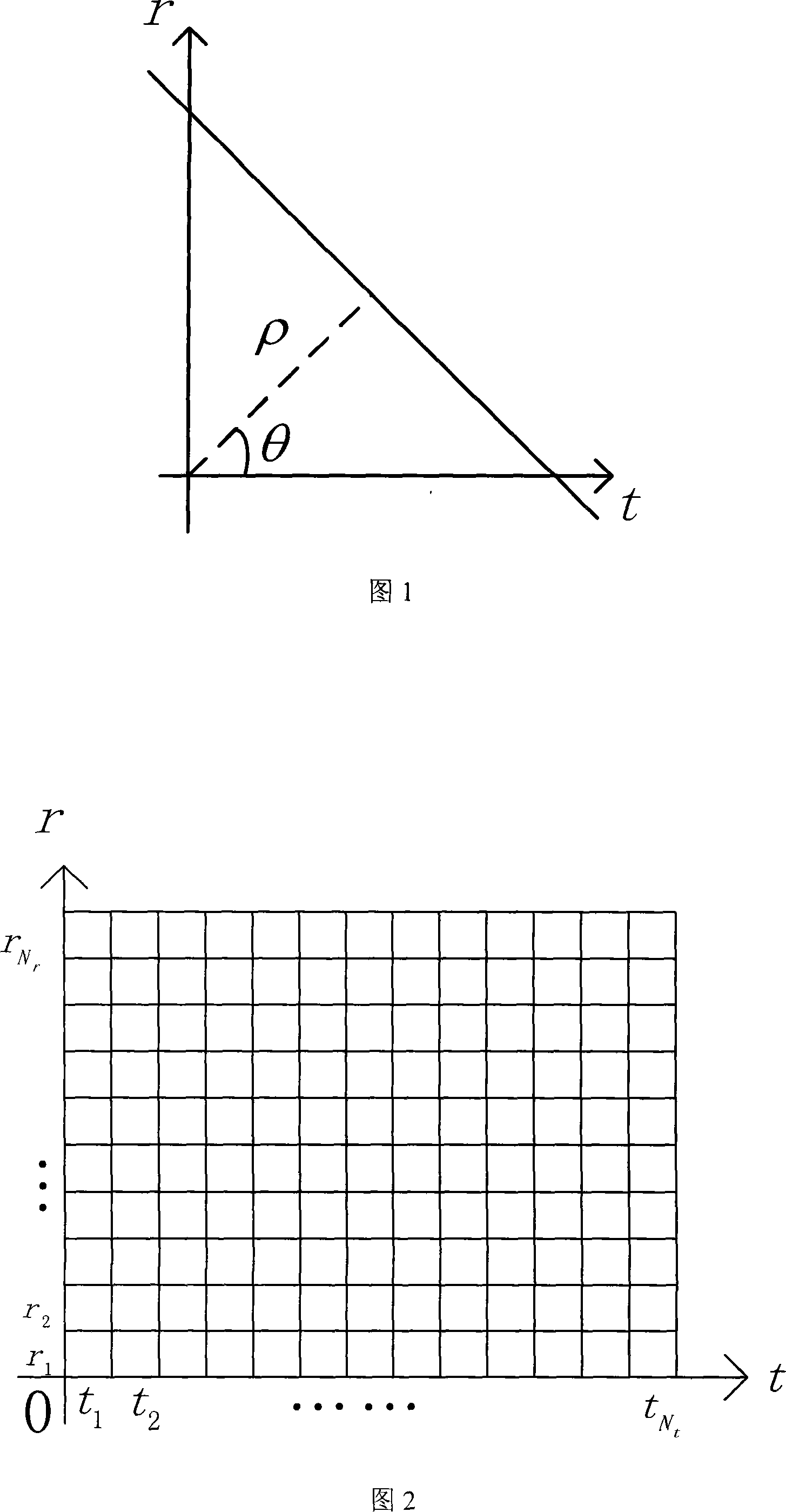
Figure 1 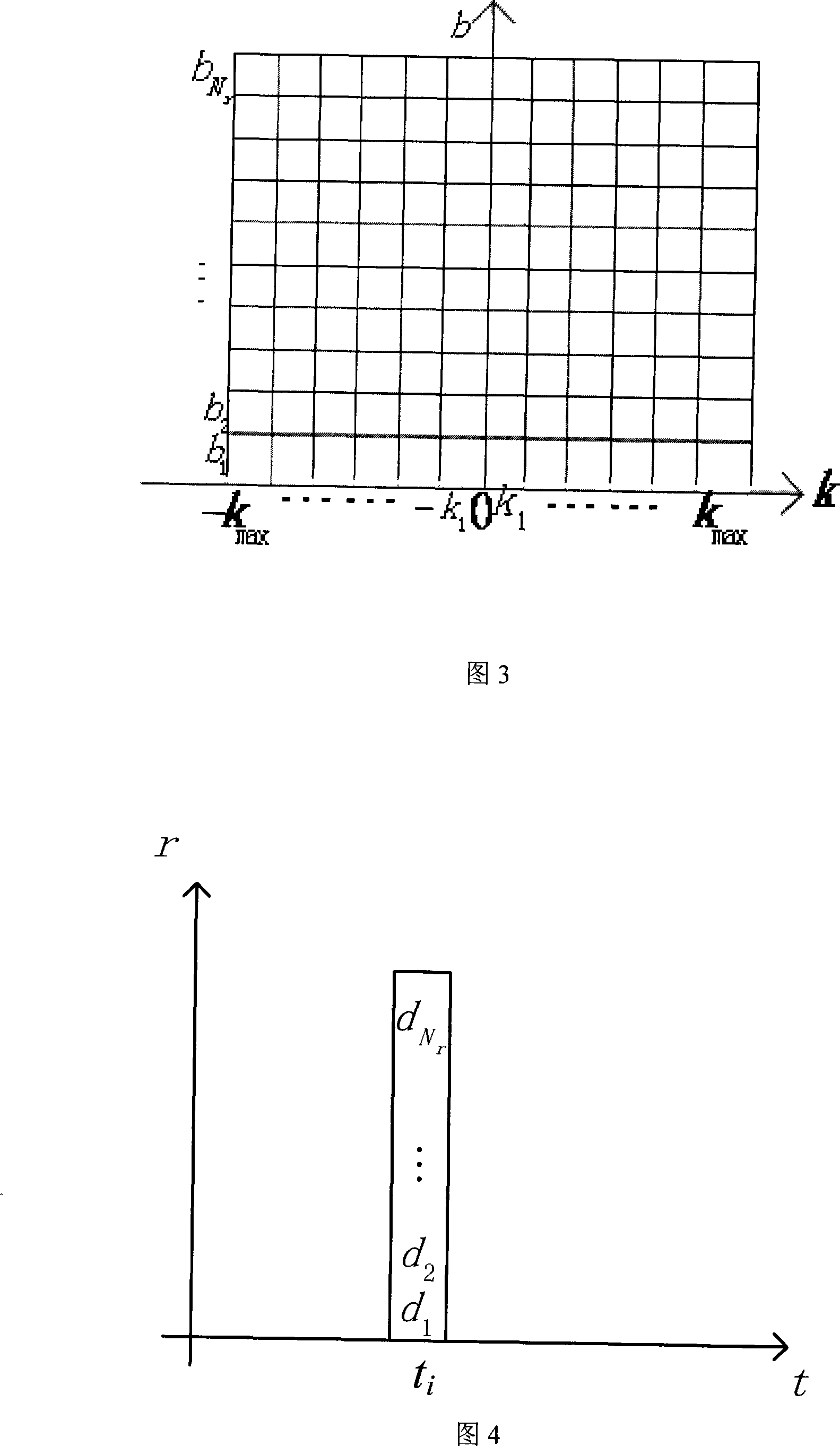
Figure 2 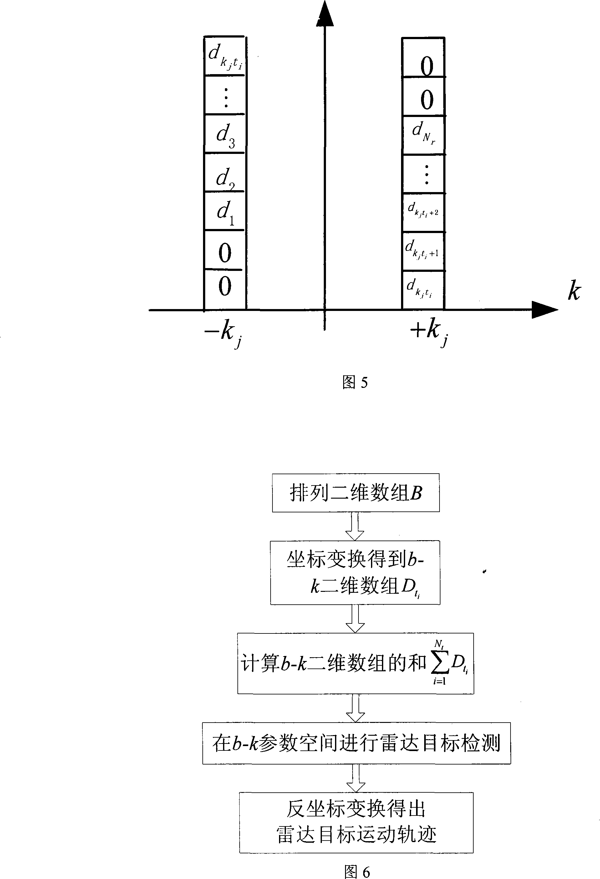
Figure 3
Abstract
Description
technical field The invention belongs to the technical field of radar, in particular to radar target detection technology. Background technique Paul Hough first proposed the Hough transform method in the document Hough P.V.C, Method and means for recognizing complex patterns, US Patent 3069654.Dec.1992. This method transforms the data space in the image processing process into the parameter space, completes the detection task by performing simple accumulation statistics in the parameter space, and describes the region boundary curve of the image with a certain parameter form that most boundary points satisfy. For images disturbed by noise or intermittent region boundaries, the Hough transform has good error tolerance and robustness. The Hough transform was originally only used for image processing. The basic idea of using the Hough transform to extract graphics in the image is: to calculate the possible trajectory of the reference point in the parameter space from the ed...