Method and apparatus for controlling rotary machines

A technology of rotating parts and controllers, used in mechanical equipment, control of mechanical energy, control of generators, etc., can solve problems such as air gap size reduction, unbalance, rotor deflection, etc.

Inactive Publication Date: 2008-07-09
GENERAL ELECTRIC CO
View PDF0 Cites 12 Cited by
  • Summary
  • Abstract
  • Description
  • Claims
  • Application Information

AI Technical Summary

Problems solved by technology

However, asymmetrical and / or transient loads on the rotor may be induced by the blades and / or other mechanisms
These asymmetrical and / or transient loads will sometimes deflect the rotor, reducing the size of the air gap and / or changing it to an unbalanced

Method used


Image

  • Method and apparatus for controlling rotary machines
  • Method and apparatus for controlling rotary machines
  • Method and apparatus for controlling rotary machines

Examples


Embodiment Construction

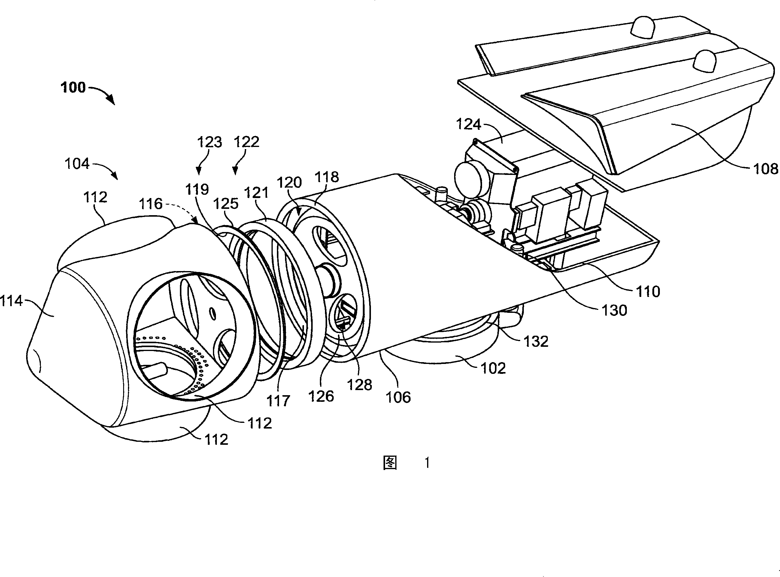
[0012] FIG. 1 is a simplified exploded view of an exemplary wind turbine generator 100 . In the exemplary embodiment, wind turbine generator 100 is a wind turbine having a horizontal axis. Alternatively, wind turbine 100 may be a wind turbine having a vertical axis. Also, alternatively, wind turbine 100 may be a 1.5 megawatt (MW) series or a 2.5 MW series wind turbine commercially available from General Electric Company of Schenectady, New York. dynamo. Alternatively, wind turbine 100 may be any wind turbine generator incorporating the invention described herein. Wind turbine 100 includes a fixture 102 extending from a tower or support surface (neither shown in FIG. 1 ). Where a tower is used, the height of the tower should be selected according to factors and conditions known in the art. Wind turbine 100 also includes hub assembly 104 , housing 106 , cover assembly 108 , and main frame 110 . Housing 106 is fixedly attached (also referred to herein as coupled or coupled) ...


PUM


Abstract

The invention provides a generator (100, 400, 500). The generator includes at least one rotating member (202, 418, 518); at least one stationary member (204) arranged to define a gap (208, 424, 524) between a portion of the rotating member and a portion of the stationary member ), wherein the gap is configured to facilitate the transfer of a controllable magnetic flux therethrough; and a gap control system (200) comprising at least one gap measurement assembly (218, 220, 222, 428, 528), at least one power a transducer (232, 234, 236) and at least one controller (224) electronically connected to the measurement assembly and the transducer and configured to adjust the size of the gap by adjusting the magnetic flux .

Description

technical field [0001] The present invention relates generally to rotating machinery and, more particularly, to methods and apparatus for controlling the size of a wind turbine generator air gap. Background technique [0002] Typically, a wind turbine generator includes a rotor with many blades. The rotor is often mounted within a casing or nacelle which is located on top of a foundation, such as a frame or tubular tower. At least some known utility-scale wind turbines (ie, wind turbines designed to provide electrical power to a utility grid) may have several 30-meter (98-foot) or larger diameter rotors. The rotor blades transform mechanical wind energy into mechanical rotational torque that drives one or more generators. These generators are sometimes, but not always, rotatably connected (coupled) to the rotor through a gearbox. The gearbox steps up the inherently low rotational speed of the turbine rotor so that the generator efficiently converts the rotational mechanic...

Claims


Application Information

Patent Timeline
Patent Type & Authority Applications(China)
IPC IPC(8): H02K7/12H02P9/00H02P9/40
CPCF03D7/02F03D7/0272F03D7/042F03D9/25F03D80/70F05B2270/502F05B2270/504F16C32/0497H02K7/09H02K49/06Y02E10/72
Inventor C·施拉姆H·吕策A·比克A·里斯贝尔格R·W·德尔梅里科
Owner GENERAL ELECTRIC CO
Why Eureka
Try Eureka