Piston for a working cylinder

A technology of working cylinders and pistons, which is applied in the direction of pistons, cylindrical pistons, plungers, etc., can solve the problems of time-consuming, high manufacturing and assembly costs, and achieve the effect of simple design

Inactive Publication Date: 2011-08-10
FESTO AG & CO KG
View PDF8 Cites 0 Cited by
  • Summary
  • Abstract
  • Description
  • Claims
  • Application Information

AI Technical Summary

Problems solved by technology

Such pistons have the disadvantage of being relatively expensive to manufacture and assemble
The individual

Method used


Image

  • Piston for a working cylinder
  • Piston for a working cylinder
  • Piston for a working cylinder

Examples


Embodiment Construction

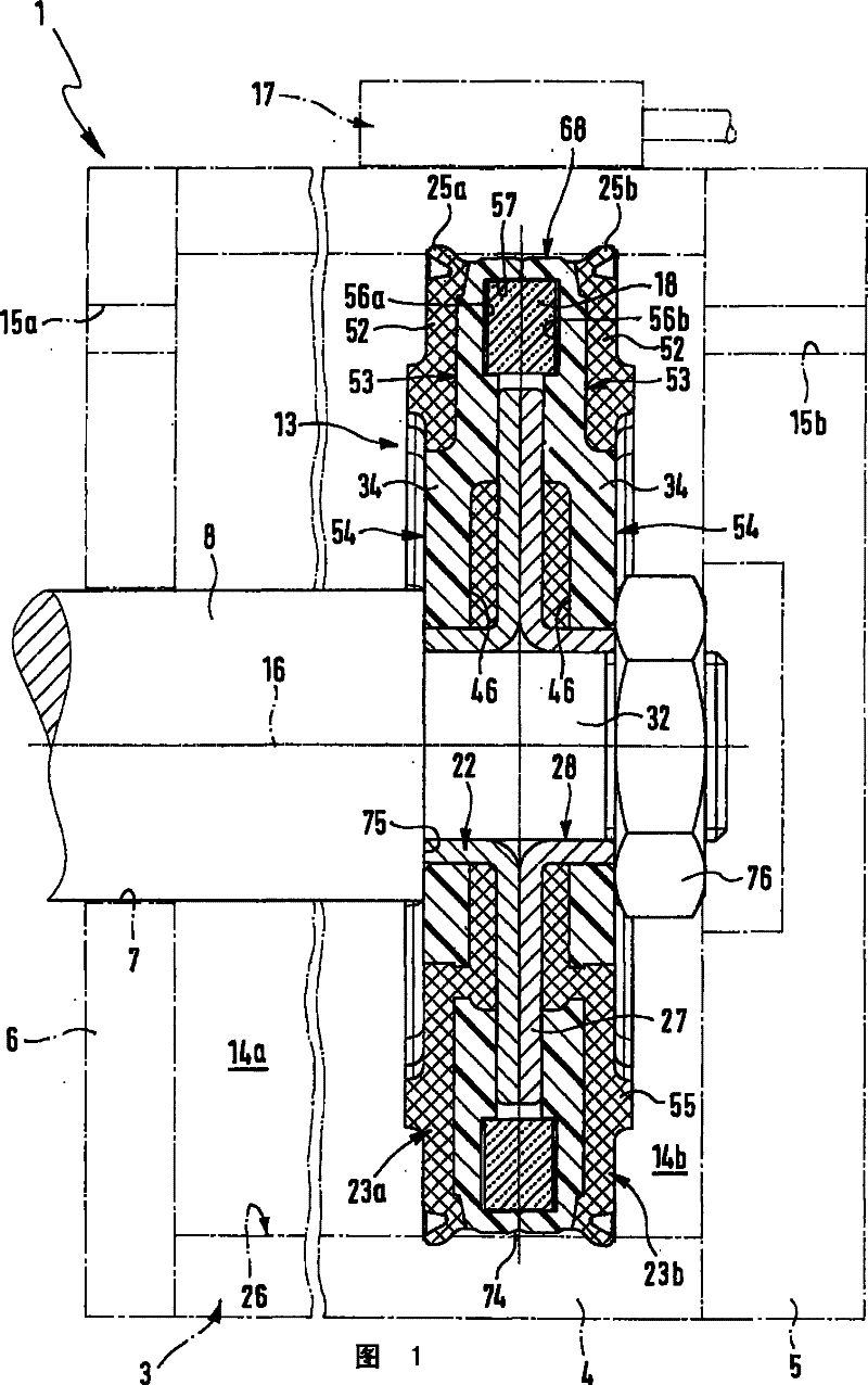
[0035] figure 1A fluid-actuated working cylinder, which is designated in its entirety with the reference numeral 1 , is shown in part only schematically and with dot-dash lines. It is especially suitable for working with compressed air, but of course it can also be propelled by another gas medium or hydraulic medium.

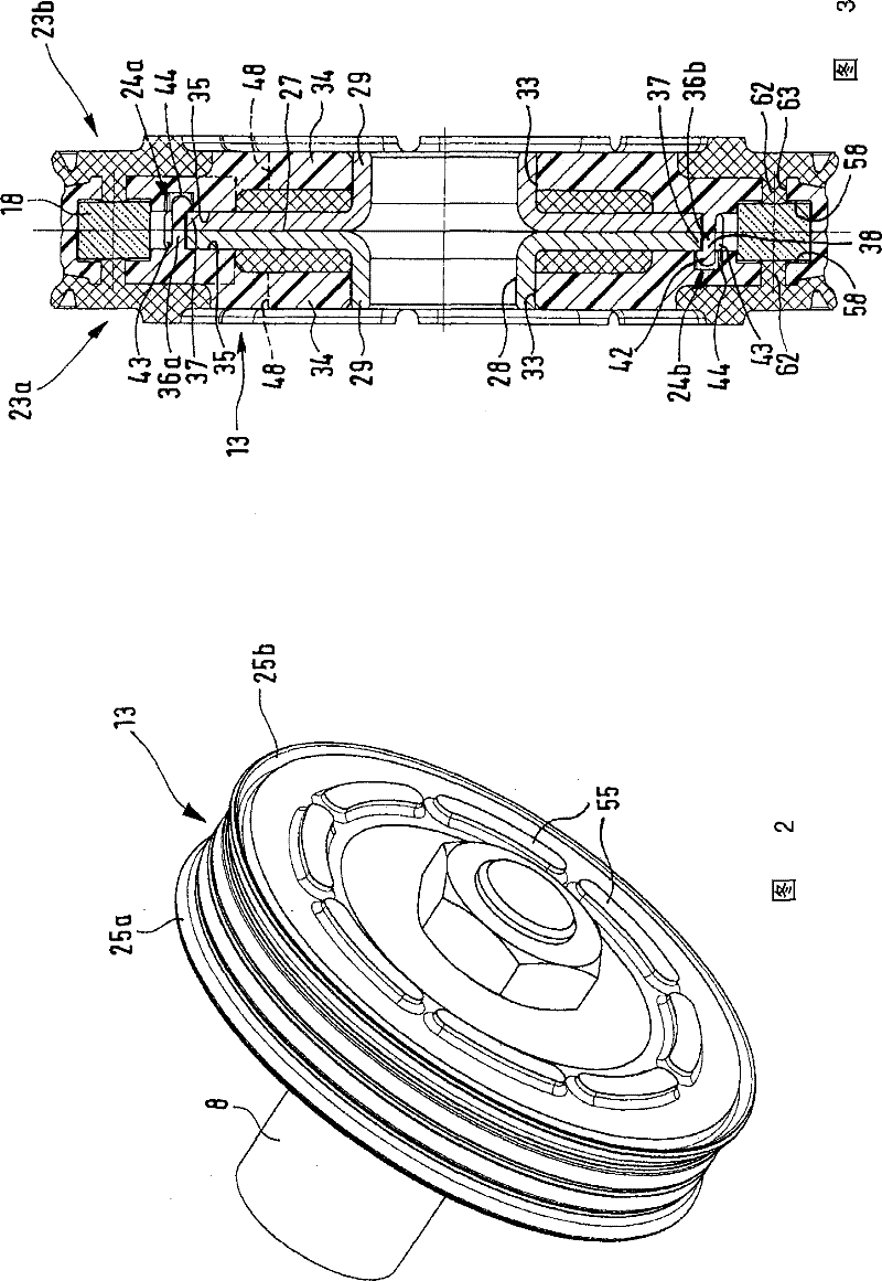
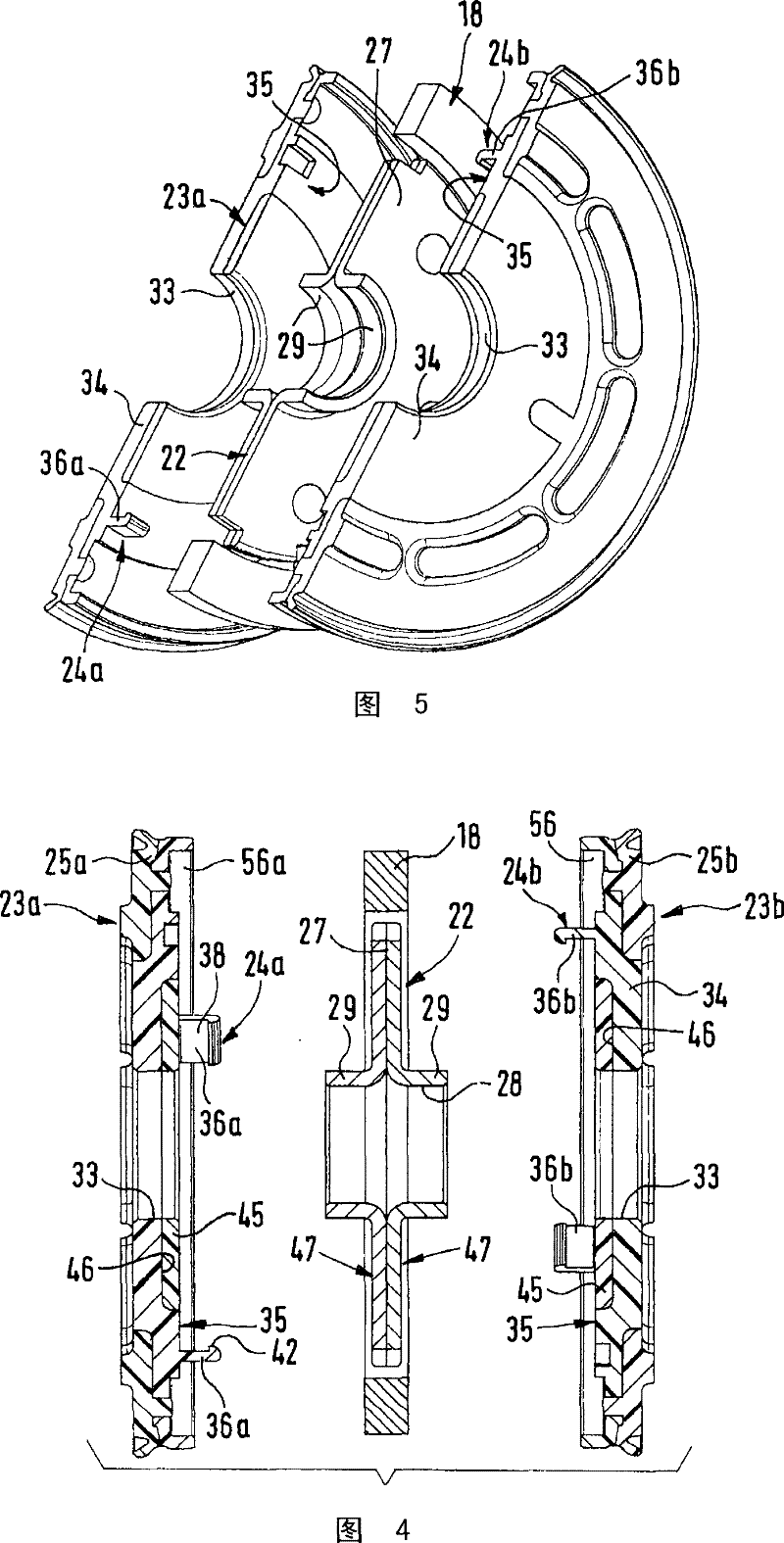
[0036] The cylinder 1 has a cylinder housing 3 with a cylinder liner 4 which is closed at the rear by an end cover 5 and at the front by a support cover 6 . The support cover is penetrated by a central through-hole 7, in which guide and sealing devices, not shown in detail, are arranged, which together with a piston rod 8 passing through the through-hole 7 play a guiding and sealing role. A piston 13 according to a preferred embodiment of the invention is attached to the end of the piston rod 8 arranged inside the cylinder housing 3, the piston dividing the interior of the cylinder housing 3 into two axially arranged The cylinder chamber 14a, 14b.

[0037] A ...


PUM


Abstract

The invention relates to a piston for a working cylinder, said piston comprising two coaxial piston elements (23a, 23b) which together surround a metallic core and at least partially consist of a plastic material, at least one of said piston elements comprising a radially outwardly arranged annular piston seal (25a, 25b). The two piston elements (23a, 23b) are independently coaxially engaged withthe metallic core (22), from opposite sides, by means of an engaging device (24a, 24b) respectively provided on each element. The entire metallic core (22) is held on the respective piston element (23a, 23b) by means of the two engaging devices (24a, 24b), such that the piston elements (23a, 23b) are axially held together by means of the metallic core (22) as a connection member.

Description

technical field [0001] The invention relates to a piston of a working cylinder with two mutually coaxial piston elements surrounding a metal core and consisting at least partially of plastic material, at least one of the piston elements having a Ring piston seal to the outside. Background technique [0002] A piston of this type known from DE 3404095 A1 has two half-piston parts, which each consist of a metal lining and a housing cast on top. For the assembly of the piston, the half-piston parts are threaded axially continuously onto the journal of the piston rod and clamped together by means of a threaded bush screwed onto the piston rod. In order to fix the half-piston parts in a rotationally fixed manner relative to one another, mutually engaging elements, known as locking devices, can additionally be provided on the contact surfaces. Since the piston is not assembled until it is mounted on the piston rod, its implementation is relatively complex and presents great diff...

Claims


Application Information

Patent Timeline
IPC IPC(8): F15B15/14F15B15/20F16J1/00F16J15/56
CPCF15B15/1447F16J15/56F15B15/1452
Inventor U·基斯H·罗里格
Owner FESTO AG & CO KG
Why Eureka
Try Eureka