
Gas combustion arrangement using circular stream

A combustion device and gas technology, applied in the direction of combustion method, combustion type, lighting and heating equipment, etc., can solve the problems of short time, large space, limited filtration capacity of purifiers, etc.

Inactive Publication Date: 2008-07-09
美迪克斯派股份公司
View PDF0 Cites 2 Cited by
  • Summary
  • Abstract
  • Description
  • Claims
  • Application Information

AI Technical Summary

Problems solved by technology

[0003] However, with the conventional combustor having the above-described simple arrangement of the heat generating portion, the exhaust gas stays in the combustor for a short period of time, and it is difficult to maintain the temperature of the combustor because the space for the heat generating portion in the combustor is huge. constant
Therefore, incomplete combustion gas containing pollutants such as dioxin may be generated and discharged into the air, which may cause social problems such as environmental pollution
[0004] Although environmental pollutants can be partly filtered by a separate purifier arranged in the rear section of the combustion chamber, the purifier has its limited filtering capacity and also requires much effort and high cost for installation and maintenance

Method used


Image

  • Gas combustion arrangement using circular stream
  • Gas combustion arrangement using circular stream
  • Gas combustion arrangement using circular stream

Examples


Embodiment Construction

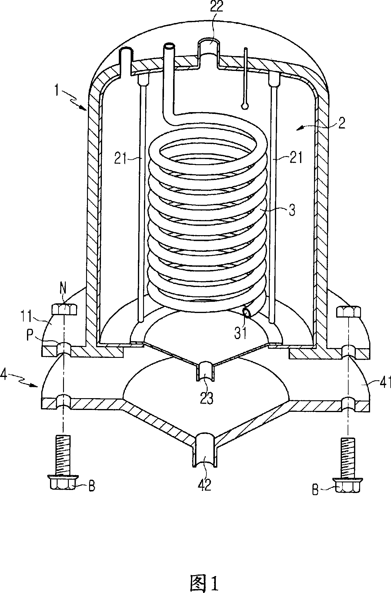
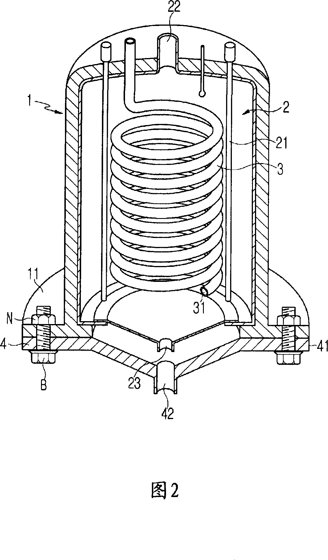
[0019] Hereinafter, the structure and operation of a gas combustion apparatus using circulating flow according to a preferred embodiment of the present invention will be described in detail with reference to the accompanying drawings.

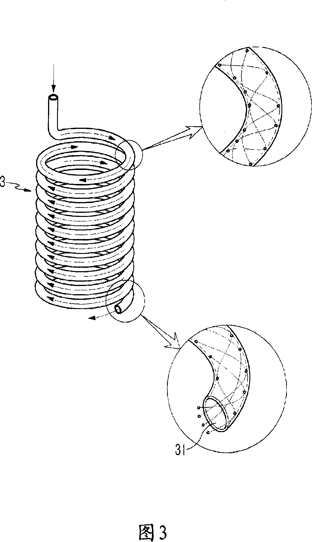
[0020] Fig. 1 is the partial dissection view of the gas combustion device utilizing circulation according to the embodiment of the present invention; Fig. 2 is the sectional view showing the combined state of the gas combustion device utilizing circulation according to the embodiment of the present invention; Fig. 3 is according to the embodiment of the present invention and FIG. 4 is a view showing an operating state of the gas combustion device using circular flow according to an embodiment of the present invention.

[0021] Referring to FIGS. 1 to 4 , a gas combustion device using a circular flow according to an embodiment of the present invention includes a housing 1 , a heat generating part 2 , a combustion tube 3 and a supporting installat...


PUM


Abstract

Disclosed is a gas combustion arrangement using a circular stream, which is capable of fully burning gas discharged from waste incinerated (by flame -broiling, high-temperature, thermal decomposition, etc.) in an incinerator provided at a front stage of the gas combustion arrangement by passing the discharged gas through a coil-shaped circular combustion pipe heated at a predetermined temperature. The present invention provides a gas combustion arrangement using a circular stream, which is capable of maximizing a combustion efficiency by prolonging stay of discharged gas, which is introduced through a coil-shaped combustion pipe, inside the gas combustion arrangement as the discharged gas is burned, forming a circular stream, inside and outside the coil-shaped combustion pipe, and burning the discharged gas through direct contact with internal and external surfaces of the combustion pipe with high temperature.

Description

technical field [0001] The present invention relates to a gas combustion device using a circular stream, which can pass through a coil-shaped circular heated combustion tube (coil-shaped circular heated combustion) which is discharged from an incinerator arranged in the front section of the gas combustion device. pipe), to completely combust the exhaust gas. More specifically, the present invention relates to a gas combustion device using a recirculation capable of prolonging the residence time of exhaust gas introduced through a helical combustion tube in the gas combustion device during combustion, The internal and external circulation is formed, and the combustion efficiency is maximized by directly contacting the internal and external surfaces of the combustion tube with high temperature to burn the exhaust gas. Background technique [0002] Conventional incineration equipment for waste treatment basically includes an incinerator for incinerating (flame-broiling) waste,...

Claims


Application Information

Patent Timeline
Patent Type & Authority Applications(China)
IPC IPC(8): F23G7/06F23G5/16
CPCF23G5/16F23G7/063F23G7/06
Inventor 郑淑镇
Owner 美迪克斯派股份公司
Learn More