Cooling structure of construction machine

A technology of construction machinery and structure, which is applied in the combination of cooling arrangement of buildings and power units, earth movers/excavators, etc., to achieve the effect of improving cooling capacity and reducing speed

Active Publication Date: 2008-07-23
KOBELCO CONSTR MASCH CO LTD
View PDF2 Cites 6 Cited by
  • Summary
  • Abstract
  • Description
  • Claims
  • Application Information

AI Technical Summary

Problems solved by technology

Moreover, the air volume is affected by the cross-sectional area of ​​the air intake passage 14, and regarding the cross-sectional area of ​​the air intake passage, the actual situation is, especially in hydraulic excavators where the space of the air suction chamber 6 is limited due to the requirement of miniaturizat

Method used


Image

  • Cooling structure of construction machine
  • Cooling structure of construction machine
  • Cooling structure of construction machine

Examples


no. 1 approach

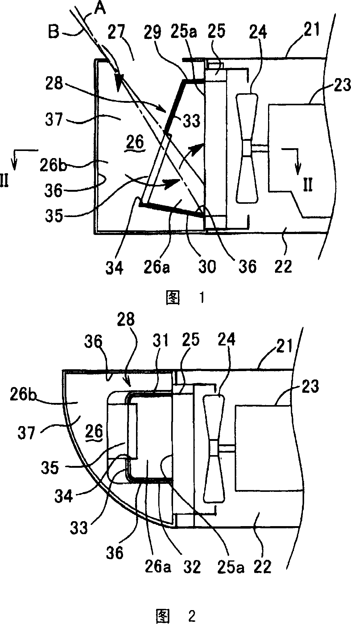
[0048] First Embodiment (Refer to FIG. 1 and FIG. 2 )

[0049] In each of the first to ninth embodiments shown in FIGS. 1 to 11 , ducts are provided as shielding members.

[0050] In the first embodiment, the following basic structure is the same as the technique shown in FIG. 13 .

[0051] (A) An engine compartment 22 covered with a cover material 21 such as an engine guard, a part of a counterweight, and an upper surface of a fuel tank is provided at the rear of the upper revolving body.

[0052] (B) Heat exchangers (one of which is shown here) 25 such as an engine 23 , a hydraulic pump not shown, a cooling fan 24 , and a radiator are provided in the engine room 22 .

[0053] (C) An air intake chamber 26 is formed on the air intake side of the heat exchanger 25 in the engine compartment 22, and a first air intake chamber for introducing air from the outside is provided on the upper surface of the air intake chamber 26 (the upper surface portion of the cover material 21). Air...

no. 2 approach

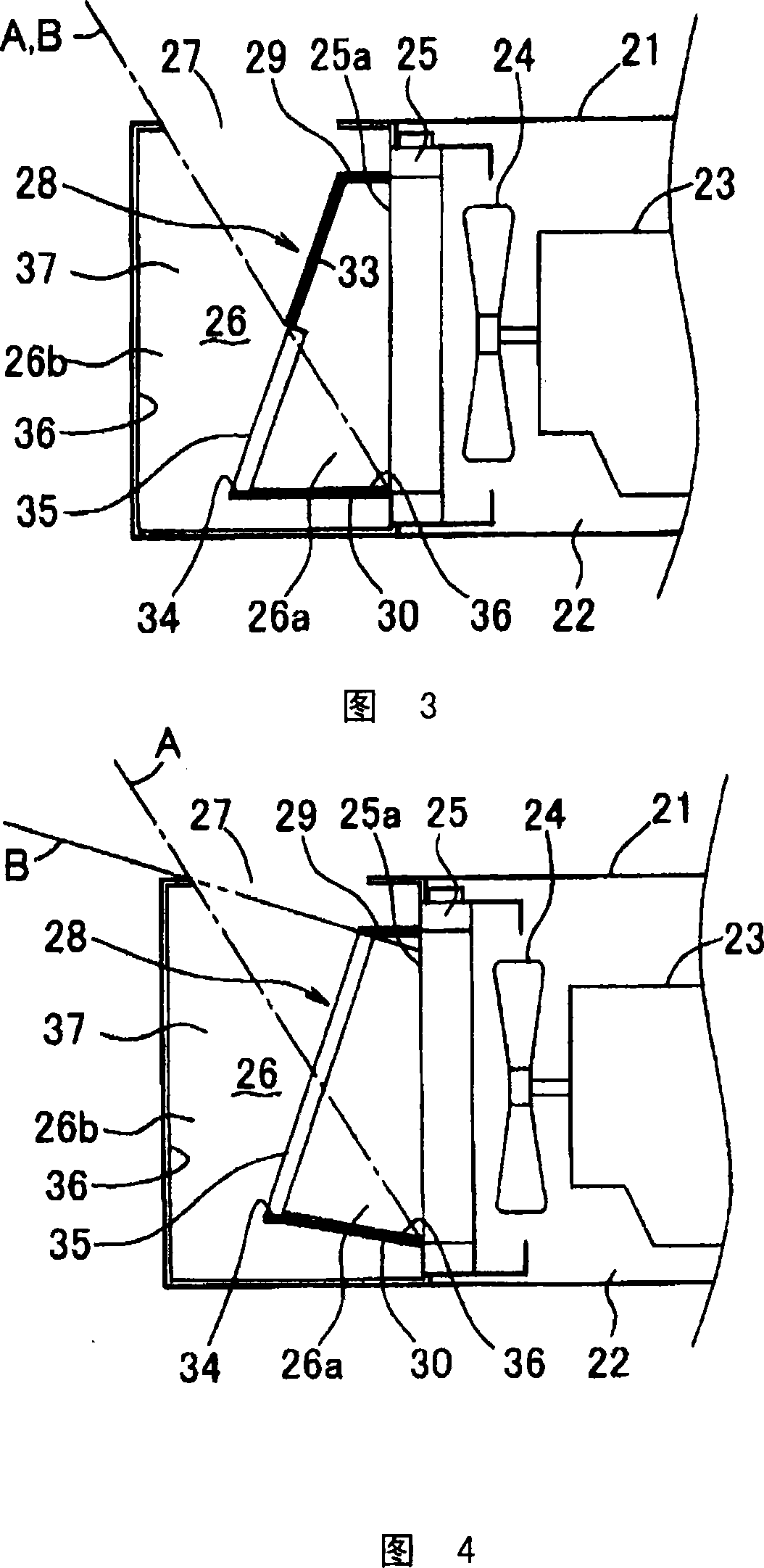
[0081] Second embodiment (refer to FIG. 3 )

[0082] In the first embodiment, it is arranged so that a part of the heat exchanger core surface 25 a cannot be directly seen from the outside through the first and second intake ports 27 , 34 .

[0083] Specifically, as shown in FIG. 1, it is arranged so that: the straight line B connecting the outermost end of the first air inlet 27 and the upper end of the second air inlet 34 is less than the straight line B connecting the outer end of the first air inlet and the heat exchanger core. The straight line A at the lower end of the surface 25a is slightly but notably on the upper side.

[0084] Thus, leakage of direct sound, which is directly discharged from the heat exchanger core surface 25a to the outside, occurs, though rarely.

[0085] In the second embodiment, as an improvement technique for this point, the second air inlet 34 is made smaller than that of the first embodiment while maintaining the same size of the second air i...

no. 3 approach

[0088] Third embodiment (refer to FIG. 4 )

[0089] In the first and second embodiments, the second suction port 34 is provided only on the suction downstream side (lower half) of the duct front portion 33 , but in the third embodiment, the duct front portion The entire surface of the is provided with a second suction port 34 . In addition, at this time, since the duct front part does not exist substantially as a surface, it is not attached with the code|symbol in FIG. 4. FIG.

[0090] According to this structure, the range directly seen from the outside of the heat exchanger core surface 25a becomes larger, so it is disadvantageous in terms of direct sound isolation, but since the sucked air can be supplied to the heat exchanger core surface 25a with the minimum resistance , so it is advantageous in terms of cooling efficiency.


PUM


Abstract

The invention provides a cooling structure of a construction machine. An engine, a cooling fan, and a heat exchanger are installed in an engine compartment covered with a cover material, and an air intake chamber is formed on an air intake side of the heat exchanger. A first suction port is provided on the upper chamber wall of the suction chamber, and a duct is provided on the front surface side of the heat exchanger core surface in the suction chamber. In the cooling structure of the construction machine based on this structure, the front portion of the duct is inclined in a direction in which the cross-sectional area of ​​the air intake passage formed between the front portion of the duct and the side surface of the cover material is largest at the upper portion and goes downward. Decrease gradually, and set the second suction port in the lower half of the front part.

Description

technical field [0001] The present invention relates to a cooling structure of a construction machine provided with a sound insulation function on an intake side of a heat exchanger that guides cooling air taken in from the outside. Background technique [0002] In construction machines such as hydraulic excavators, there are Japanese Patent Application Laid-Open No. 2006-206034 and Japanese Patent Laid-Open No. 2006-207576 (hereinafter referred to as Patent Documents 1 and 2, respectively) as technologies for improving the sound insulation performance on the suction side. ) is well known. [0003] A hydraulic excavator is used as an example to illustrate the technology. 13 and 14 are explanatory sectional views showing the cooling structure of the rear portion of the upper revolving body of the hydraulic excavator. [0004] An engine compartment 2 covered with a cover material 1 such as an engine guard, a part of a counterweight, and an upper surface of a fuel tank is pro...

Claims


Application Information

Patent Timeline
IPC IPC(8): B60K11/04
CPCE02F9/00B60K11/08E02F9/0866
Inventor 木下伸一木村康正满田正彦中岛一谷内智也
Owner KOBELCO CONSTR MASCH CO LTD
Why Eureka
Try Eureka