High speed electrohydraulic open and close valve driven directly by ultra-magnetostriction actuator

A technology of giant magnetostrictive and giant magnetostrictive rods, applied in the direction of valve lift, valve details, valve devices, etc., can solve the problems of complex temperature rise structure, slow dynamic response speed and low driving efficiency of giant magnetostrictive rods , to improve the response speed and control precision, fast dynamic response speed and compact structure

Inactive Publication Date: 2008-07-23
HARBIN INST OF TECH
View PDF0 Cites 19 Cited by
  • Summary
  • Abstract
  • Description
  • Claims
  • Application Information

AI Technical Summary

Problems solved by technology

[0003] The present invention solves the problem of existing actuators in electro-hydraulic switching valves, which suppress the temperature rise of giant magnetostrictive rods, have complex structure, unreasonable design, slow dynamic response speed, low control precision, large volume, poor reliability, and poor driving efficiency. low problem, thus providing a high-speed electro-hydraulic switching valve directly driven by a giant magnetostrictive actuator

Method used


Image

  • High speed electrohydraulic open and close valve driven directly by ultra-magnetostriction actuator
  • High speed electrohydraulic open and close valve driven directly by ultra-magnetostriction actuator
  • High speed electrohydraulic open and close valve driven directly by ultra-magnetostriction actuator

Examples


specific Embodiment approach 1

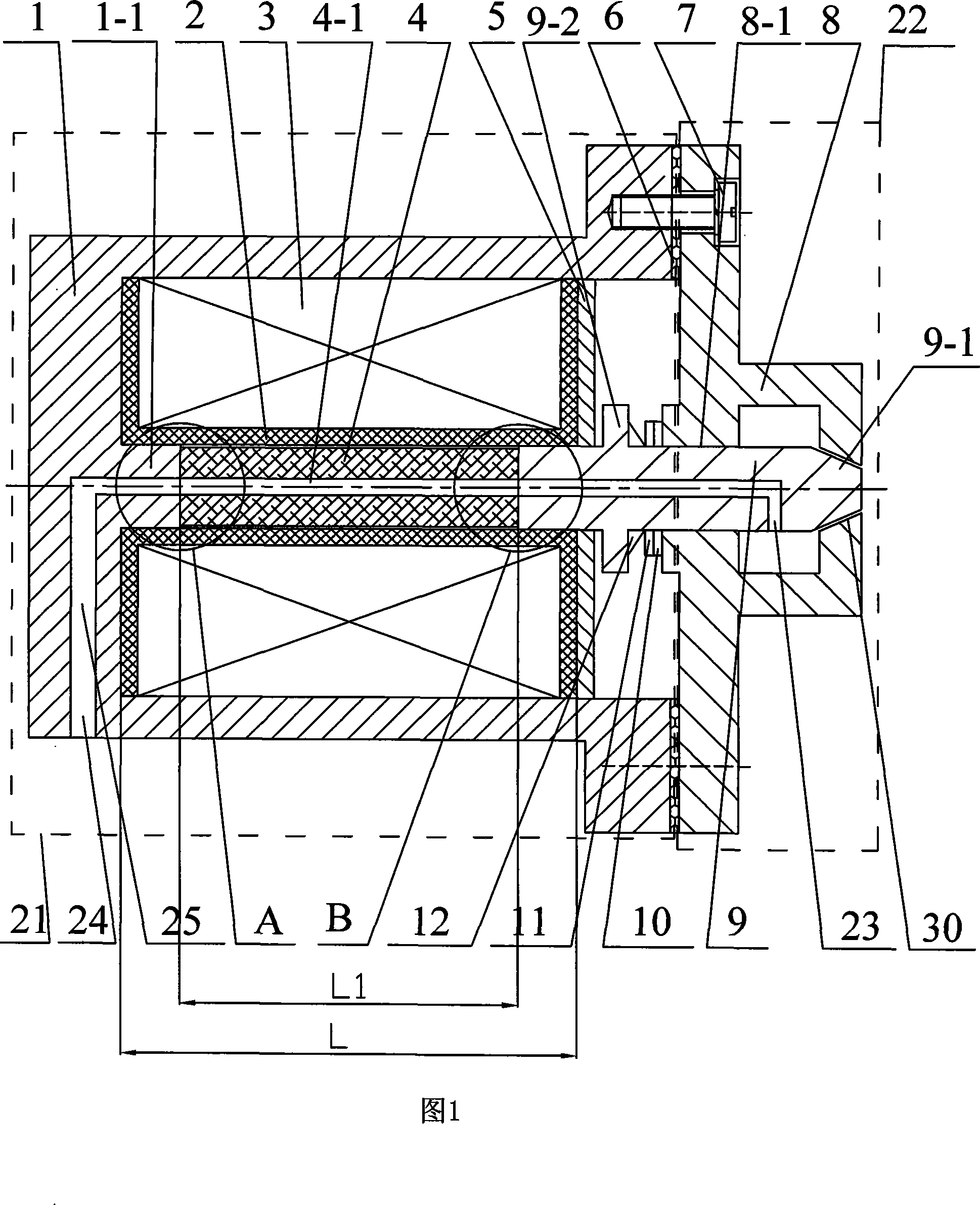
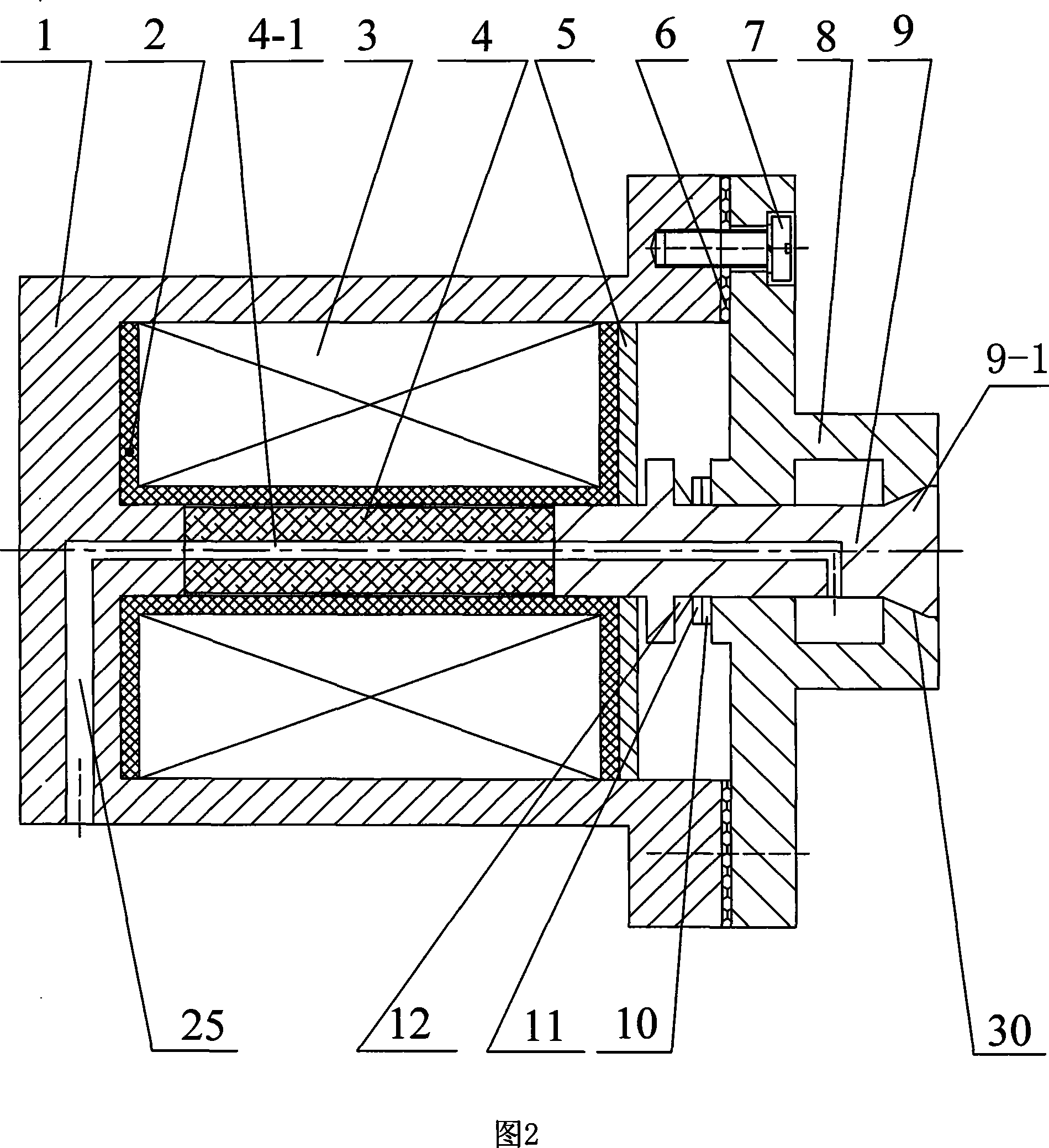
[0007] Embodiment 1: As shown in Figure 1 and Figure 2, the high-speed electro-hydraulic switching valve directly driven by the giant magnetostrictive actuator of this embodiment consists of a giant magnetostrictive actuator (Giant MagnetostrictiveActuator-GMA) 21 and a switch valve 22, the giant magnetostrictive actuator 21 is made up of an actuator housing 1, a coil bobbin 2, a drive coil 3, a giant magnetostrictive rod 4, and a baffle 5, and the switch valve 22 is made up of a valve body 8. The valve core 9 is composed of; the front end of the valve core 9 is installed in the valve body 8, the valve core 9 passes through the through hole 8-1 on the valve body 8, and the rear end of the valve core 9 is connected with the actuator housing 1 The bottom end is fixed together by the giant magnetostrictive rod 4, the front end of the valve core 9 is in contact with the valve 30 on the valve body 8, the coil bobbin 2 is set on the giant magnetostrictive rod 4, and the driving coil ...

specific Embodiment approach 2

[0010] Specific embodiment two: as shown in Figure 1 and Figure 5, the drive coil 3 described in this embodiment is composed of three (odd number) concentric coils with the same inner and outer diameters, and each coil is wound around the coil in turn from left to right on skeleton 2. With such a design, the internal magnetic field distribution of the giant magnetostrictive rod 4 can be improved and the uniformity of the magnetic field can be improved by adopting different current drives in sections. Other components and connections are the same as those in the first embodiment.

specific Embodiment approach 3

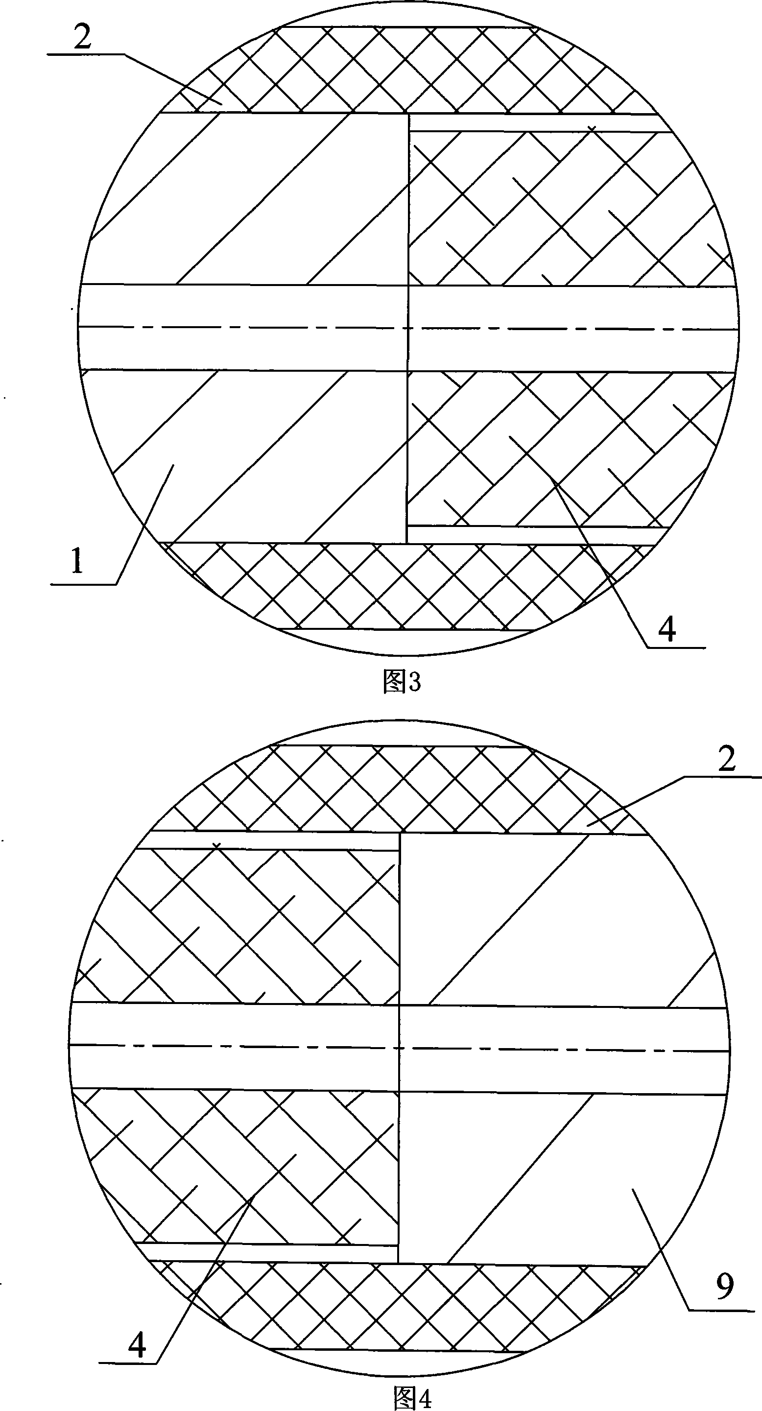
[0011] Specific embodiment three: as shown in Fig. 1, Fig. 3 and Fig. 4, a boss 1-1 is provided on the bottom end of the actuator housing 1 in this embodiment, the boss 1-1, the The boss 1-1 is fixedly connected to the giant magnetostrictive rod 4, and the cross-sectional radius of the boss 1-1 and the valve core 9 is greater than that of the giant magnetostrictive rod 4. Such a design can improve the uniformity of the magnetic field on the contact surface of the giant magnetostrictive rod 4 . Other components and connections are the same as those in the first embodiment.


PUM


Abstract

The invention relates to a high-speed switch valve, in particular to a high-speed electrohydraulic switch valve driven by an giant magnetostrictive actuator, which solves the problems of the prior actuator in the switch valve that the temperature rise of a magnetostrictive rod is restrained, the structure is complicated, the design is not reasonable, the dynamic response speed is slow, the control precision is low and the drive efficiency is low. A coil frame (2) is sleeved on the magnetostrictive rod, a drive coil is wound on the coil frame (2), a liquid flowing inlet (24) is disposed on a side wall of an actuator casing, a liquid flowing outlet (23) is positioned on the side wall of a valve core (9), the liquid flowing inlet (24) is communicated with the liquid flowing outlet (23) through an axial hole (4-1) of the magnetostrictive rod (4) and the actuator casing (1) is sealed with a valve body (8). The high-speed switch valve has the advantages that the temperature rise of the magnetostrictive rod can be restrained, the structure is simple, the design is reasonable, the dynamic response speed is fast, the flow rate control precision is high and the switch frequency is high.

Description

technical field [0001] The invention relates to a high-speed switch valve, in particular to a high-speed electro-hydraulic switch valve directly driven by a giant magnetostrictive actuator. Background technique [0002] As a bridge connecting the electrical part and the hydraulic part, the electro-hydraulic switch valve is the core component of the electro-hydraulic control system. Its basic components are electro-mechanical converters, hydraulic pre-stages, hydraulic amplification stages and appropriate feedback mechanisms. In the traditional electro-hydraulic control system, the electromagnet actuator is generally used as the electro-mechanical converter, but its large size, slow response speed (5 ~ 10ms), low control accuracy, and complex structure cannot adapt to today's high-speed high-precision Electro-hydraulic control system needs. To improve the performance of the electro-hydraulic control system, the bandwidth and response speed of its electro-mechanical converte...

Claims


Application Information

Patent Timeline
Patent Type & Authority Applications(China)
IPC IPC(8): F16K1/00F16K31/06F16K49/00
Inventor 李立毅寇宝泉张成明吴红星
Owner HARBIN INST OF TECH
Why Eureka
Try Eureka