Modular rolling mill

A rolling mill and combined technology, applied in the direction of cantilever rolling mill stand, metal rolling stand, metal rolling stand, etc., can solve complex and expensive problems

Inactive Publication Date: 2008-07-30
PRIMETALS TECH USA
View PDF10 Cites 9 Cited by
  • Summary
  • Abstract
  • Description
  • Claims
  • Application Information

AI Technical Summary

Problems solved by technology

Although mechanically robust and advantageously flexible, such a combined setup is relatively complex and expensive to purchase and subsequently maintain compared to block mills

Method used


Image

  • Modular rolling mill
  • Modular rolling mill
  • Modular rolling mill

Examples


Embodiment Construction

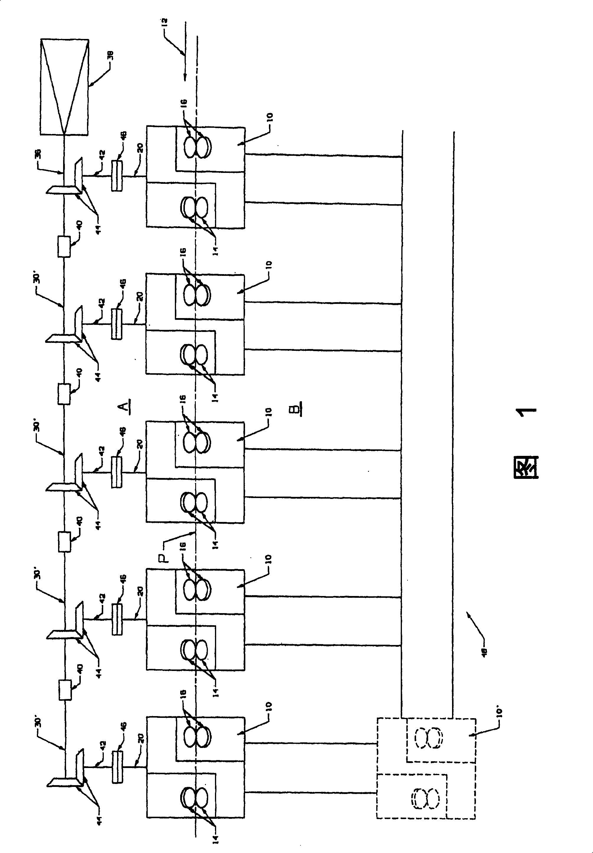
[0017] Referring to Fig. 1, a combination rolling mill according to the present invention comprises a plurality of separate rolling units 10 arranged along a mill pass line "P". The direction of rolling is indicated by arrow 12 . Each rolling unit has at least two pairs of work rolls 14, 14 and 16, 16 configured to define elliptical and circular rolling channels. Each pair of consecutive rolls is staggered at 90° to implement twist-free rolling of long products such as rods and rods.

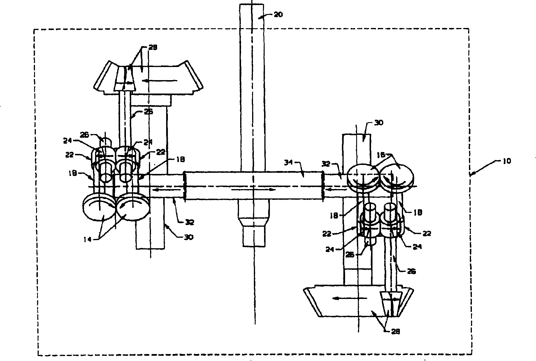
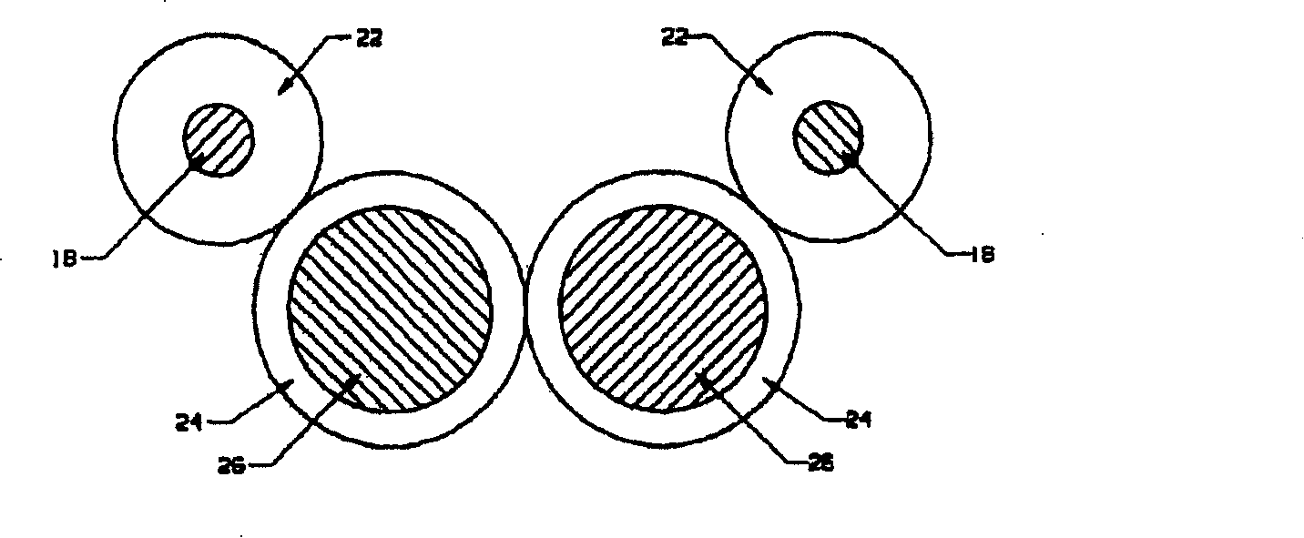
[0018] additionally refer to figure 2 with 3 , it can be seen that the work rolls are mounted on the roll shaft 18 and the intermediate drive system is included in the rolling unit to mechanically couple the roll shaft to the input shaft 20 . The input shafts are parallel and project towards the first side "A" of the roll line. The intermediate transmission system includes gears 22 on roller shafts meshing with intermeshing gears 24 on shafts 26 , one of the two shafts 26 being connected to...


PUM


Abstract

A combination rolling mill includes a plurality of separate rolling units arranged along a mill pass line. Each rolling unit comprises at least two pairs of work rolls defining elliptical and circular rolling channels and supported on roll axes staggered at 90° relative to each other. The rolling units comprise an intermediate drive system configured to connect the roller shafts to parallel input shafts protruding from the respective rolling unit towards the first side of the pass line. A single transmission power axis is parallel to the roll line and on a first side of the roll line. The output shaft is mechanically coupled to the power shaft by a bevel gear set. An output shaft protrudes laterally from the power shaft roll line and is connected to the input shaft of the rolling unit by a separable coupling.

Description

technical field [0001] This invention relates generally to rolling mills for the production of longer products such as rods and rods, and more particularly to providing an improved combination rolling mill. Background technique [0002] Block-type rolling mills are known, as disclosed, for example, in US Pat. These rolling mills are mainly used as finishing trains in wire rod rolling mills and are widely used around the world. Block mills consist of a series of rolling stands arranged sequentially to roll an alternating sequence of elliptical / circular channels, with the rolling axes of the circular rolling stands relative to the rolling axes of the elliptical rolling stands Staggered at 90° to roll the product without twisting. [0003] Typically, rolling stands with circular and elliptical rolling passages are staggered on opposite sides of the mill pass line and are mechanically coupled to corresponding parallel power shafts driven at different speeds by a common mill dr...

Claims


Application Information

Patent Timeline
Patent Type & Authority Applications(China)
IPC IPC(8): B21B1/18B21B35/10B21B35/12B21B35/14B21B35/02
CPCB21B35/02B21B1/18B21B13/001B21B13/005B21B31/08B21B31/10B21B2013/003B21B39/16B21B2027/083
Inventor T·M·肖尔M·A·波勒
Owner PRIMETALS TECH USA
Why Eureka
Try Eureka