Emergency braking arrangement for automobiles

An emergency braking, automobile technology, applied in the direction of brakes, braking components, vehicle parts, etc., can solve the problems of road damage, high hydraulic pressure, affecting braking effect, etc., to increase adhesion, prevent car accidents, save money The effect of braking time

Inactive Publication Date: 2008-07-30
刘小平
View PDF1 Cites 12 Cited by
  • Summary
  • Abstract
  • Description
  • Claims
  • Application Information

AI Technical Summary

Problems solved by technology

[0003] Although the above technical solution solves the problem of increasing the friction with the ground through the anti-skid rake after the car brakes suddenly, it can relatively shorten the sliding distance, but it is impossible to increase the hydraulic pressure in the pipeline instantly by using hydraulic transmission for braking. , it takes a period of time from the lifting process of the hydraulic pressure to the complete realization of the brake, which affects the braking effect. In addition, the patent application is equipped with a double row of comb-shaped hard metal knives in the structural design. In this structural design, the metal The knife is used when braking on different roads. If it travels on asphalt road or concrete road, it will cause damage to the road.

Method used


Image

  • Emergency braking arrangement for automobiles
  • Emergency braking arrangement for automobiles
  • Emergency braking arrangement for automobiles

Examples


Embodiment 1

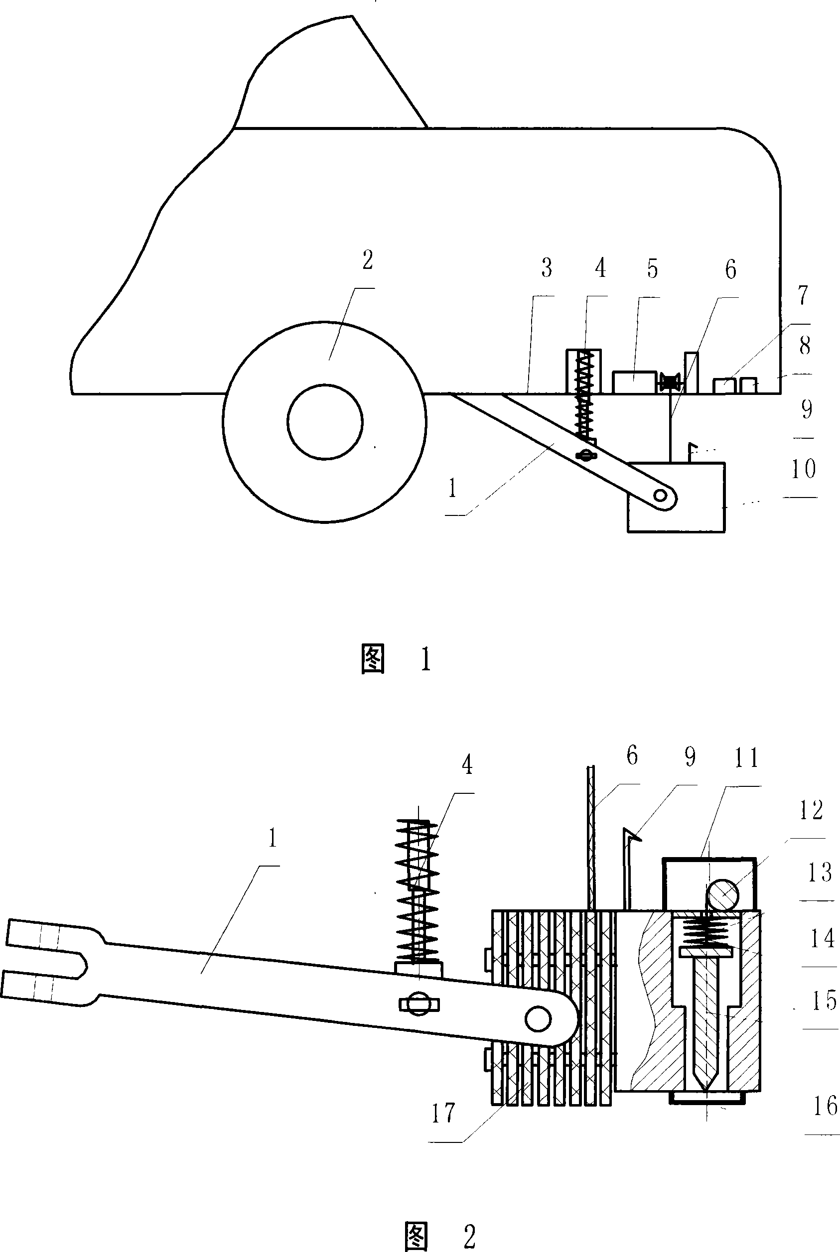
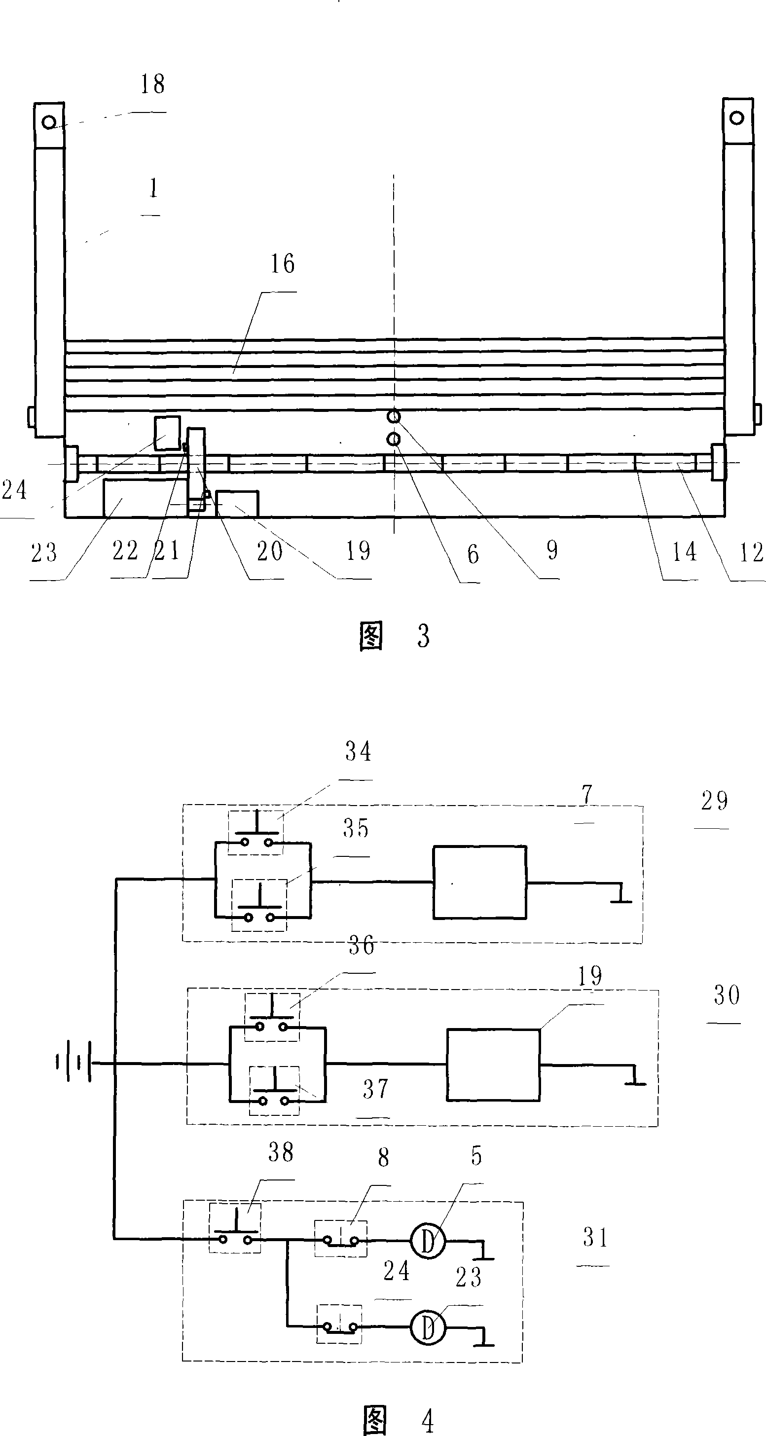
[0021] With reference to accompanying drawing 1, Fig. 2, Fig. 3, Fig. 4, present embodiment comprises the fixing frame that is fixedly installed in the rear bottom of automobile, dragging anchor type brake, dragging anchor type brake lifting device, it is characterized in that described dragging anchor type brake is set There is a dragging anchor arm 1, and a dragging anchor brake main body 10 is connected with the dragging anchor arm 1. A plurality of friction-resistant and high-temperature-resistant brake composite material plates 17 are installed on the dragging anchor brake main body 10, and are fixed with fastening nails 18. Close to the brake composite material plate 17, ten retractable brake nails 15 are arranged side by side, and the brake nails 15 are connected with a brake nail lifting device. 1 is provided with a booster spring 4, and the upper end of the booster spring 4 is fixedly connected to the bottom plate 3 of the rear box. Be provided with motor I5, solenoid...

Embodiment 2

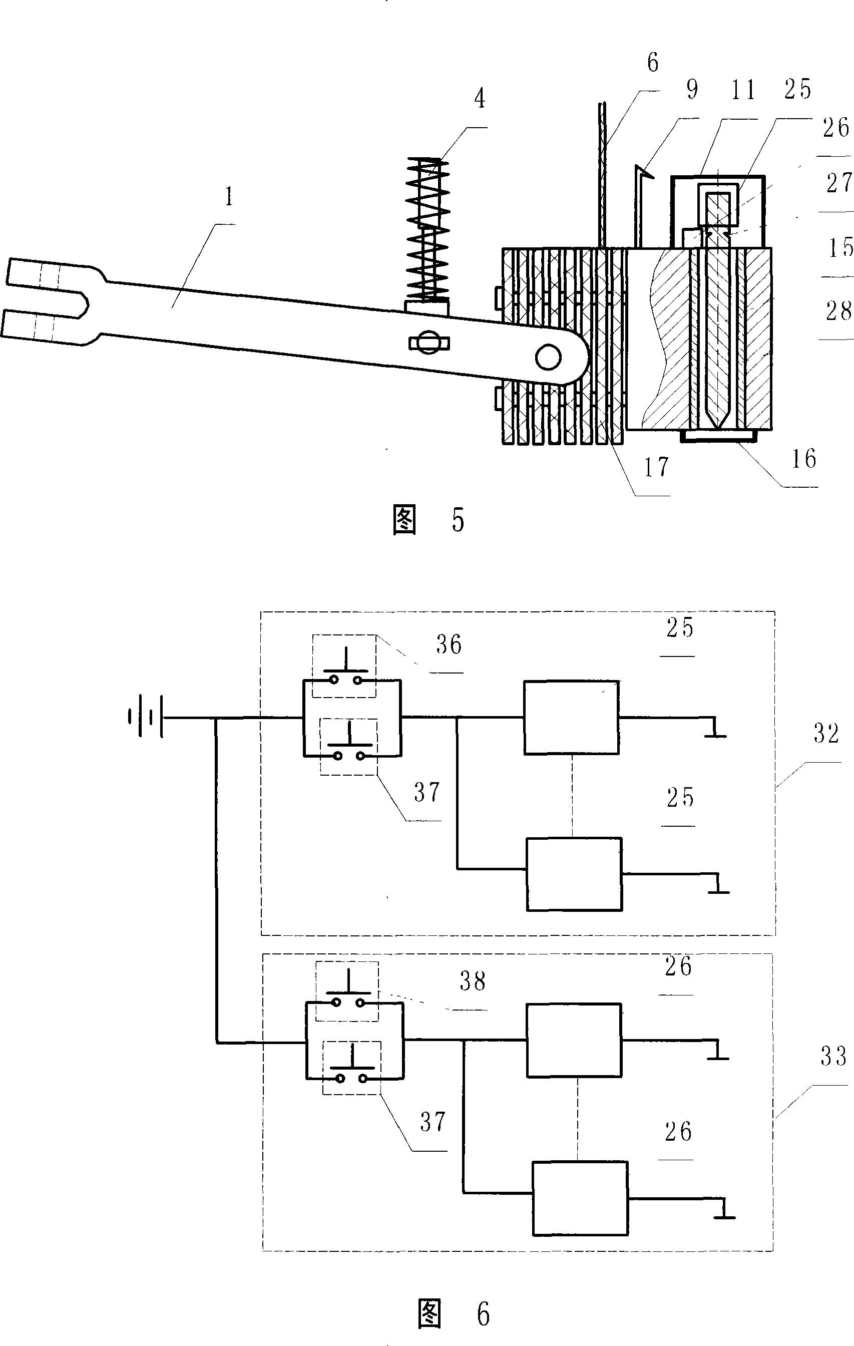
[0030] With reference to Fig. 5, shown in Fig. 6, compared with embodiment 1, the difference of this embodiment is that the brake nail elevating device, its structure is in the upper part of drag anchor type brake main body 10, each brake nail 15 is equipped with Electromagnetic valve III25 and electromagnetic valve IV26, brake nail positioning groove 27 is provided on the top of brake nail 15, and magnetic isolation sleeve 28 is provided in the brake nail whereabouts hole.

[0031] It works as follows:

[0032] When ice and snow appear on the road surface, utilize manual switch III38 or road surface detection switch 37, energize to make solenoid valve IV26 action, solenoid valve IV26 pin is extracted from brake nail positioning groove 27, and brake nail 15 falls.

[0033] When there is no need for the brake pin to brake, the manual switch II36 or the road surface detection switch 37 can be used to energize the solenoid valve III25, and the brake pin 15 will be lifted up rapid...

Embodiment 3

[0036] Compared with Embodiment 1, the difference of this embodiment is that the upper part of the main body 10 of the drag anchor brake is provided with an upper dust cover 11 to prevent dust accumulation and ensure the normal operation of components.


PUM


Abstract

The invention relates to an automobile brake device, in particular to an auxiliary urgency braking device on an automobile, which comprises a fixed frame fixedly installed on a back bottom of the automobile and a drag anchor typed brake. The invention is characterized in that: the brake of drag anchor type has a drag anchor typed brake body, a plurality of composite brake plates and expansible brake nails are arranged on the drag anchor typed brake body, wherein, the brake nails are connected with a lifting device of the brake nails; the drag anchor typed brake has a lifting device of the drag anchor typed brake. The invention is controlled by an electric circuit, so the braking time can be saved and the occurrence of car accident can be effectively avoided. The drag anchor typed brake body is provided with pressure springs as well as a plurality of the composite brake plates of wear and high temperature resistance and the expansible brake nails, thus effectively increasing friction and fully playing effective brake function; in addition, when the brake nails are not used, the road is unlikely to be damaged.

Description

Technical field: [0001] The invention relates to an automobile brake device, in particular to an auxiliary automobile emergency brake device. Background technique: [0002] Usually when the vehicle is running at high speed, if an emergency occurs, due to the high speed, the braking force of the original braking system is limited during emergency braking, and the inertia of the vehicle body is large, so the vehicle cannot stop instantly, but has to slide for a certain distance, resulting in frequent accidents. , in order to find a solution that can effectively make the car brake quickly and ensure safety, some design schemes have proposed adding an auxiliary braking device to the original braking system of the car, as disclosed in patent application 94241256.7 The anti-skid device for emergency brakes of automobiles consists of two parts, a mechanical part and a hydraulic system. Install an anti-skid device on the girder of the car, the device has a hydraulic energy storage ...

Claims


Application Information

Patent Timeline
Patent Type & Authority Applications(China)
IPC IPC(8): B60T1/14
Inventor 刘小平
Owner 刘小平
Why Eureka
Try Eureka