

Device for loading machines handling bulk materials
A loading device, technology for bulk materials, applied in the field of devices for loading machines handling bulk materials, able to solve problems such as efficiency limitations, and achieve the effect of efficient driving, simple and reliable method
- Summary
- Abstract
- Description
- Claims
- Application Information
AI Technical Summary
Problems solved by technology
Method used
Image

Examples
Embodiment Construction
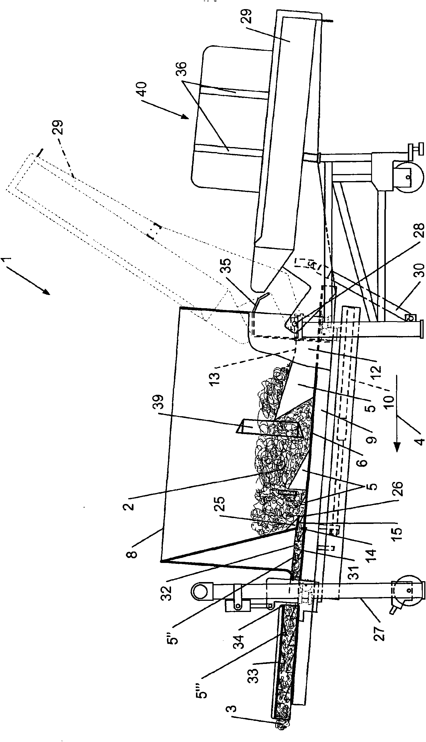
[0037] According to the invention and as shown in the accompanying drawings in particular figure 1 with 5 The shown loading device 1 is used to load a machine (such as a fiber cutter) with fibers, which can continuously extract fibers from a stock pile 2 to form a belt 3 having the same characteristics as the material capable of being absorbed by the cutter. Corresponding to the cross section of the cross section, the loading device can also move the belt 3 uniformly towards the cutter until the belt is picked up by the conveyor belt of the cutter. The extraction of the material takes place by means of a first set of protruding elements 5 penetrating the heap, at least some of which are movable, and by their movement organize the fibers to form the belt 3 and make the belt 3 in the driving direction 4 up and forward.
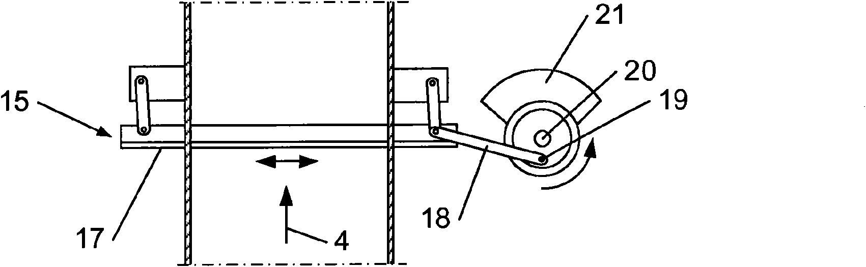
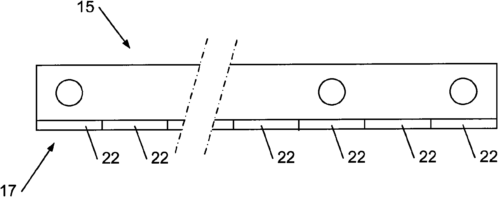
[0038] In the device of this exemplary embodiment, these protruding elements 5 are hooks fixed (preferably detachable) to two movable plates 6 and a fixed pla...
PUM
 Abstract
Description
Claims
Application Information