Wiper blade for cleaning panes in particular of motor vehicles

Active Publication Date: 2013-12-12
ROBERT BOSCH GMBH
View PDF7 Cites 0 Cited by
  • Summary
  • Abstract
  • Description
  • Claims
  • Application Information

AI Technical Summary

Benefits of technology

[0008]A very simple and reliable method in which welded joints are effectively avoided is provided by the method according to the invention for producing a wiper blade whereby the spring rails are inserted individually or togeth

Problems solved by technology

In everyday use, this welded joint is exposed to extreme conditions and must withstand high torques and vibrations in different weather conditions.
Especially in the case of wiper blades which are produced

Method used


Image

  • Wiper blade for cleaning panes in particular of motor vehicles
  • Wiper blade for cleaning panes in particular of motor vehicles
  • Wiper blade for cleaning panes in particular of motor vehicles

Examples


Example

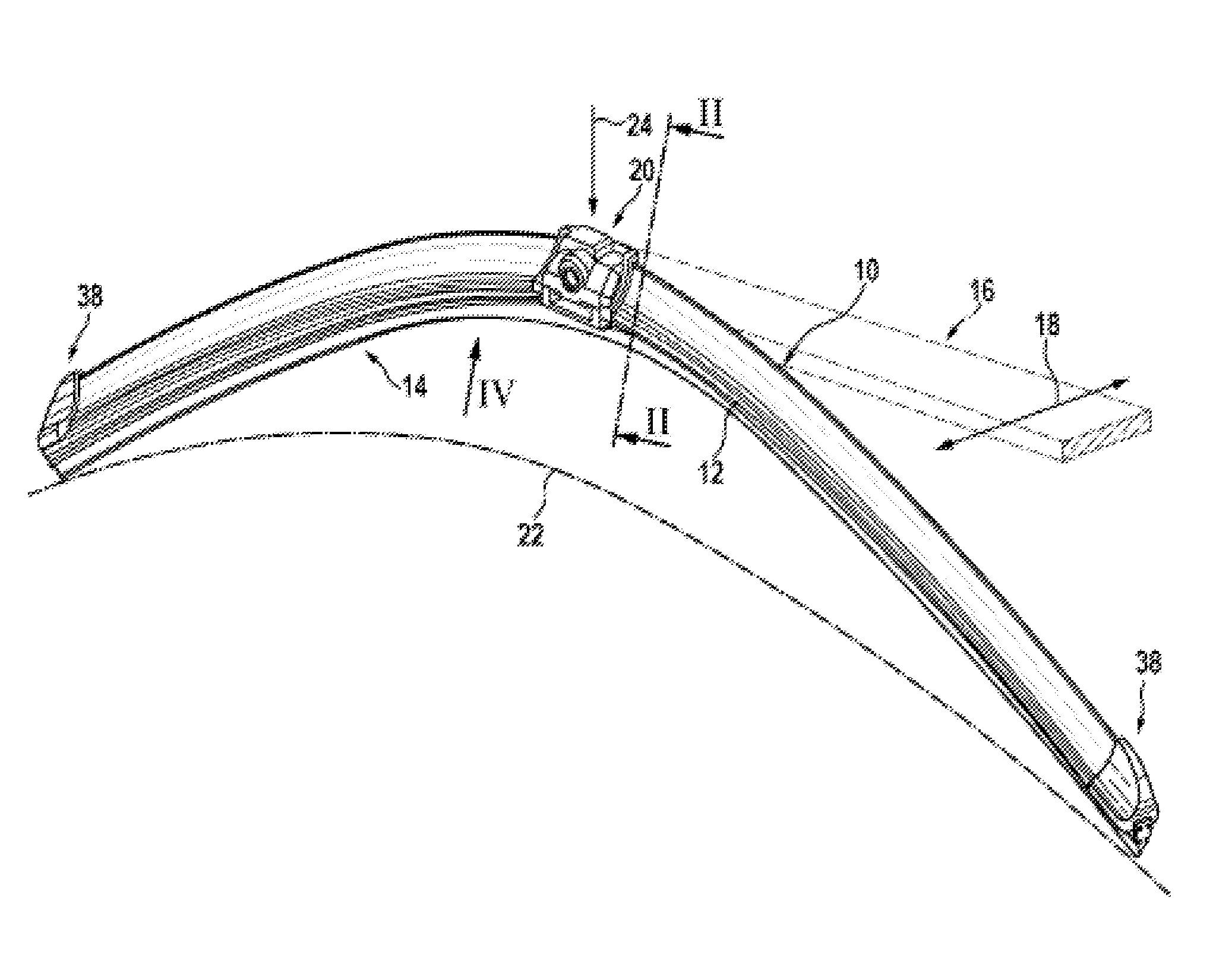
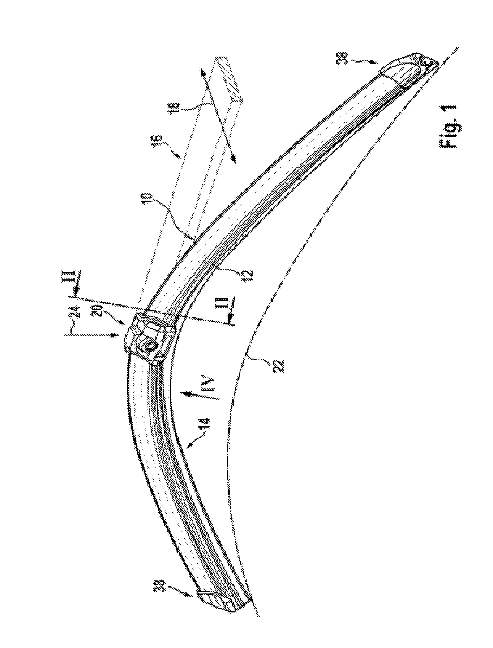
[0015]A wiper blade 10 shown in FIG. 1 has a supporting element 12 (FIGS. 1 and 2), which is elongated in the manner of a band, which has spring elasticity and on the lower band side 13 of which, that facing the window, an elongated wiper strip 14 having rubber elasticity is fastened parallel to the longitudinal axis. Arranged on the upper band side 11, that facing away from the window, of the supporting element 12, which can also be referred to as a spring rail, in the central section of said supporting element, is the wiper blade-side part 15 of a connection device, by means of which the wiper blade 10 can be releaseably connected in an articulated manner to a wiper arm 16 indicated in chain-dotted lines in FIG. 1. The wiper arm 16, which is driven backward and forward in the direction of a double arrow 18 in FIG. 1, is loaded in the direction of an arrow 24 toward the window to be wiped—for example toward the windshield of a motor vehicle—the surface of which is indicated in FIG....


PUM

PropertyMeasurementUnit
Thicknessaaaaaaaaaa
Sizeaaaaaaaaaa
Widthaaaaaaaaaa

Abstract

The invention relates to a production method and to a wiper blade for wiping panes, in particular motor vehicle panes, comprising a retaining element (12) for receiving a wiper strip (14), said retaining element having two spring rails (28, 30) which are separated from each other by a gap (32) and to which a connecting device (20) is fixed. The connecting device has a wiper blade-side part (15) with claw-like receiving portions (34, 36) that engage around the retaining element (12) at least in some regions. Each of the receiving portions (34, 36) has an internal width (42) that expands in the direction of the gap (32).

Description

BACKGROUND OF THE INVENTION[0001]In the case of wiper blades for wiping windows, in particular motor vehicle windows, comprising a supporting element for receiving a wiper strip which supporting element has two spring rails which are separated from one another via a gap and to which a connection device is fastened, which connection device has a wiper blade-side part with claw-like receptacles which engage around the supporting element at least in certain regions, the supporting element is supposed to ensure as uniform as possible distribution of the wiper blade contact pressure emanating from the wiper arm against the window over the entire wiping area wiped by the wiper blade. By means of an appropriate curvature of the supporting element when under no load—i.e. when the wiper blade is not resting against the window—the ends of the wiper strip, which is laid fully on the window during the operation of the wiper blade, are subjected to a load in the direction of the window by the su...

Claims


Application Information

Patent Timeline
IPC IPC(8): B60S1/40
CPCB60S1/3856B60S1/3879Y10T29/49826B60S2001/3898B60S1/40B60S1/3896
Inventor VANDERHEYDEN, GERT
Owner ROBERT BOSCH GMBH
Why Eureka
Try Eureka