Electronic card connector

Inactive Publication Date: 2005-09-01
SPEED TECH
View PDF5 Cites 0 Cited by
  • Summary
  • Abstract
  • Description
  • Claims
  • Application Information

AI Technical Summary

Benefits of technology

[0010] According to an aspect of the present invention, the electronic card connector has two metallic arms, which is electrically connected to the printed circuit board using a simple and reliable method.
[0011] The electronic card connector of the present invention comprises an isolation chassis and a pair of metallic arms. The isolation chassis is made of an insulation material. The isolation chassis comprises a plurality of conductive terminals. A metallic arm is respectively fixed onto each of two ends of the isolation chassis. Each of the metallic arms extends downwardly and has a grounding

Problems solved by technology

For these increased functionalities, the circuit and electronic component within the electronic products are accordingly complicated.
While using the electronic products, interference among the components within the complicated circuit usually occurs undesirably impacting the quality of the electronic products.
The two ends of the isolation case are designed to be inserted into the metallic arm and therefore this would easily cause cumulative structural intolera

Method used


Image

  • Electronic card connector
  • Electronic card connector
  • Electronic card connector

Examples


Embodiment Construction

[0023] Reference will be made in detail to the preferred embodiments of the invention, examples of which are illustrated in the accompanying drawings. Wherever possible, the same reference numbers are used in the drawings and the description to refer to the same or like parts.

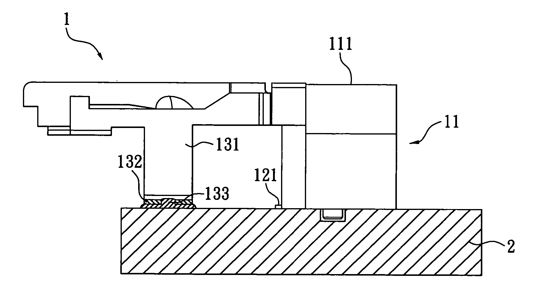
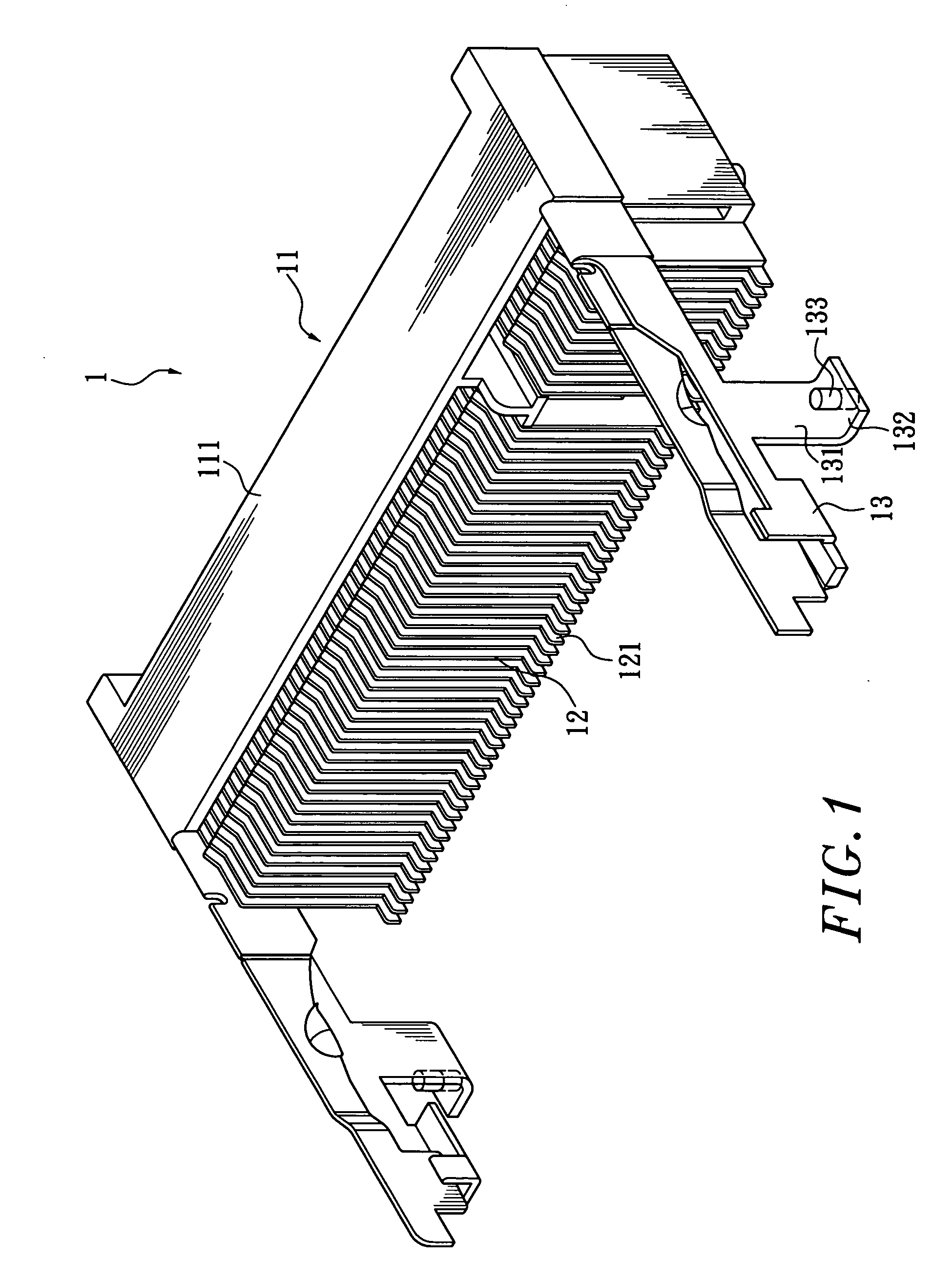
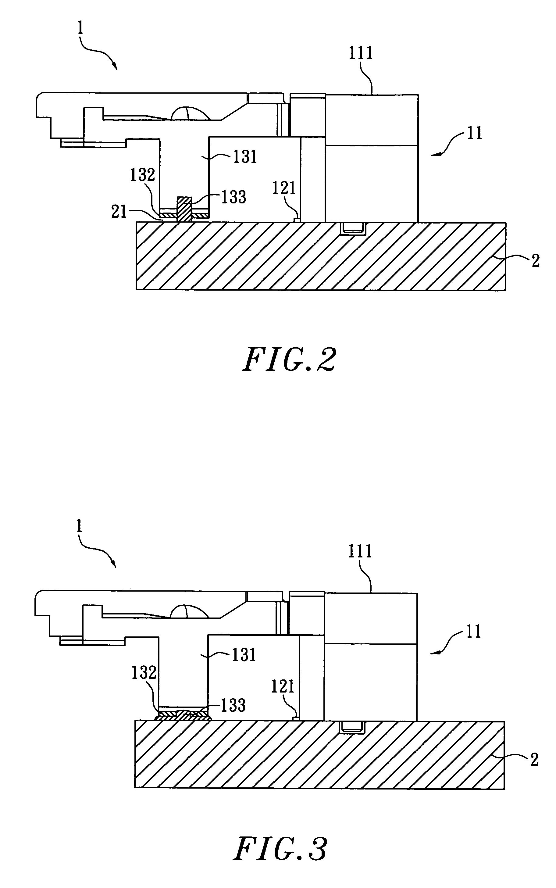
[0024] Referring to FIG. 1, an elevational view of an electronic card connector according to a preferred embodiment of the present invention is shown. The electronic card connector 1 of the present invention comprises an isolation chassis 11 and a base 111, which comprises a plurality of conductive terminals 12 penetrating therethrough. A distal end of each of the conductive terminal 12 comprises a welding portion 121. The two sides of the base 111 comprises parallel metallic arms 13 extending respectively, and each of the metallic arms 13 has a grounding portion 131 that extends downwardly. The grounding portion 131 is bent to form a welding portion 132, which has a low melting point conductive metal 133 that...


PUM


Abstract

The electronic card connector of the present invention comprises an isolation chassis and a pair of metallic arms. The isolation chassis is made of an insulation material. The isolation chassis comprises a plurality of conductive terminals. A metallic arm is respectively fixed onto each of two ends of the isolation chassis. Each of the metallic arms extends downwardly and has a grounding portion and a welding portion for welding securely to the circuit board. Before attaching the electronic card connector to the circuit board, the welding portion of the metallic arm, which has a low melting point conductive metal, reduces the vertical height on the circuit board, when it gets liquefied due to heat in the convection reflow oven, and thus the connecting point on the circuit board and the welding portion of the metallic arm are electrically connected through the solder.

Description

BACKGROUND OF THE INVENTION [0001] 1. The Field of the Invention [0002] The present invention relates to an electronic card connector, and more particularly relates to an electronic card connector having a chassis and metallic arms extending from two sides of the chassis. [0003] 2. Description of the Related Art [0004] Nowadays the electronic products, such as computers, cellular phones, digital cameras and so on, are being popularly used. The functions of these products as well as the peripheral products thereof have been substantially increased. For these increased functionalities, the circuit and electronic component within the electronic products are accordingly complicated. While using the electronic products, interference among the components within the complicated circuit usually occurs undesirably impacting the quality of the electronic products. A filtering circuit or the like may be used to avoid or reduce such interferences. The circuit or electronic component used for av...

Claims


Application Information

Patent Timeline
IPC IPC(8): H01R12/00H01R43/02H05K3/34
CPCH01R43/0263H05K3/3426H01R12/7029H05K2201/1084H05K2201/10984H05K2201/10189Y02P70/50
Inventor LIN, PO-HSIUNG
Owner SPEED TECH
Why Eureka
Try Eureka