Diffluence orientation air supply type computer cabinet

A computer case, air supply technology, applied in electrical digital data processing, instruments, digital data processing parts, etc., can solve the problems of waste of electric energy, weak effect of high-heat parts receiving wind, etc., and achieve the effect of high cooling efficiency

Inactive Publication Date: 2008-07-30
SICHUAN UNIV
View PDF0 Cites 16 Cited by
  • Summary
  • Abstract
  • Description
  • Claims
  • Application Information

AI Technical Summary

Problems solved by technology

The disadvantage of this design is: the effect of each high-heating accessory receiving wind is too weak; if the power of the chassis cooling fan is increased to increase the wind force in th

Method used


Image

  • Diffluence orientation air supply type computer cabinet

Examples


Embodiment Construction

[0010] The present invention will be further described below in conjunction with drawings and embodiments.

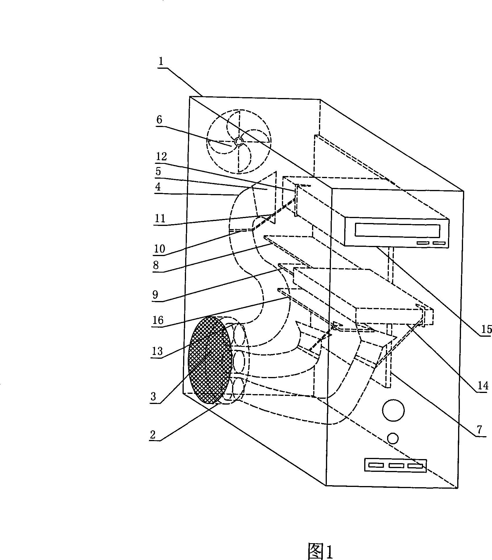
[0011] The split-flow positioning air-supply computer case includes a casing 1, an air inlet drum 2, a dust-proof net 3, an air guide pipe 4, an air supply port 5, an exhaust fan 6, a pull ring 10, a pull wire 11, a positioning clip 12 and an air distribution branch pipe 13.

[0012] Wherein, the exhaust fan 6 is located on the box plate on the rear side of the box body 1, the air intake drum 2 is located on the left box panel of the box body 1, the dustproof net 3 is located on the outside of the air intake drum 2, and 3-6 air distribution branch pipes 13 are located on the left side of the box body 1. The side on the air inlet drum 2 towards the inside of the box body 1 is integrated with the air inlet drum 2. One end of the air guide pipe 4 is connected with the air distribution branch pipe 13, and the other end is connected with the neck of the air outlet 5. The pull...


PUM


Abstract

The invention relates to a computer case, in particular to a split positioning air-blowing computer case, which comprises a case body, an air inlet blower, a dust screen, an air guide duct, air supply ports, an exhausting fan, a pull-tab, a tightening wire, positioning clamps and air-splitting branch ducts. The invention is characterized in that the air inlet blower is positioned on the left wall of the case body, a plurality of air-splitting branch ducts are positioned at the case body-facing side of the air inlet blower, one end of the air guide duct is connected with the air-splitting branch ducts and the other end thereof is connected with the neck of the air supply ports, the pull-tab is covered over the air guide duct, two ends of the tightening wire are connected with the pull-tab and the positioning clamps respectively, the positioning clamps are respectively fastened on each heater inside the case body, and each air supply port is arranged oppositely to each heater inside the case body. The invention can systemically distribute the air flow inside the case body to ensure the existence of high-speed air flow on the surface of each heater, and has higher cooling efficiency than the prior art.

Description

technical field [0001] The invention relates to a computer case, in particular to a split-flow positioning air-supply type computer case. Background technique [0002] In the existing computer case, except that the CPU has a special cooling facility, other accessories that generate high heat all rely on the air flow produced by the same case cooling fan in the case to take away a part of the heat. The disadvantage of this design is: the effect of each high-heating accessory receiving wind is too weak; if the power of the chassis cooling fan is increased to increase the wind force in the chassis, most of the flowing air will be directly discharged without passing through the high-heating accessories in the chassis Outside the chassis, resulting in a waste of electric energy. Contents of the invention [0003] In order to solve the deficiencies of the prior art, the present invention provides a shunt-positioned air-supply computer case in which all heat-generating component...

Claims


Application Information

Patent Timeline
IPC IPC(8): G06F1/20
Inventor 梁德富
Owner SICHUAN UNIV
Why Eureka
Try Eureka