Disk device and disk loading mechanism
A disk loading and conveying mechanism technology, applied in the direction of recording information storage, instruments, etc., can solve the problems of complex structure, large number of parts, high manufacturing cost, etc., achieve low manufacturing cost, prevent complex structure, and simple structure
- Summary
- Abstract
- Description
- Claims
- Application Information
AI Technical Summary
Problems solved by technology
Method used
Image

Examples
Embodiment approach 1
[0032] The configuration and operation of the disk device according to Embodiment 1 of the present invention will be described with reference to FIGS. 1 to 19 .
[0033]
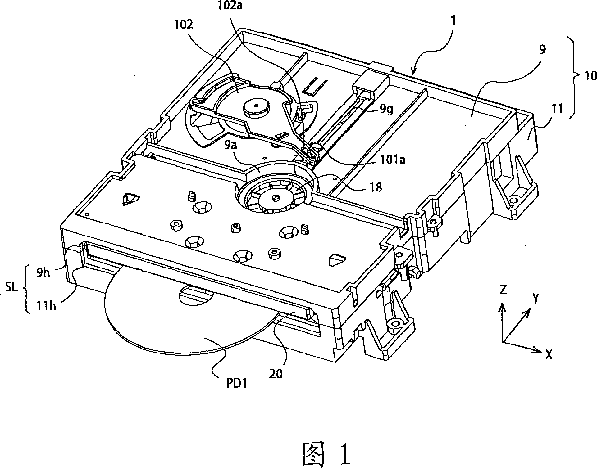
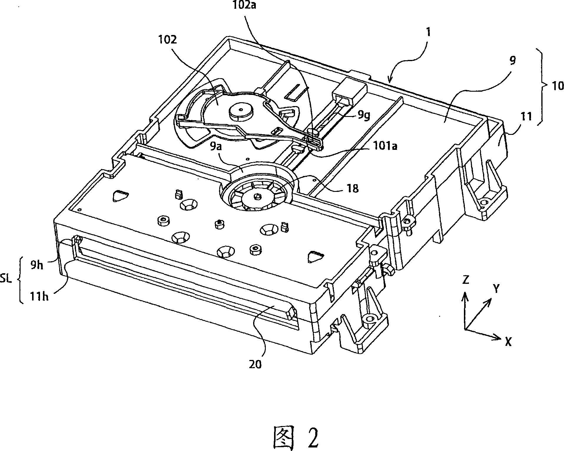
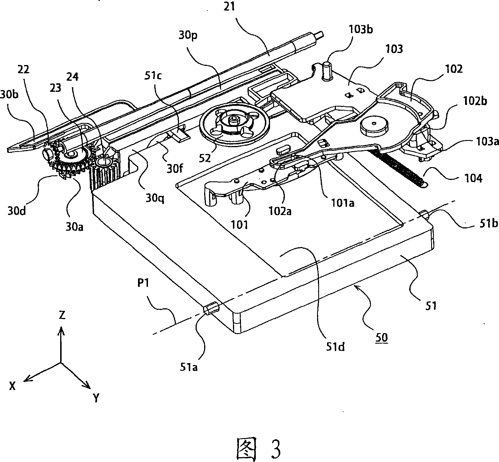
[0034] 1 and 2 are perspective views showing the external configuration of the disk device 1 viewed obliquely from above. FIG. 1 shows a state in which an optical disk PD1 having a diameter of 8 cm is stored in the disk device 1 , and FIG. 2 shows a state in which the optical disk PD1 is stored in the disk device 1 . FIG. 3 is a perspective view showing main structural components inside the disk device 1 .
[0035] In the following description, for convenience of description, the direction parallel to the storage and discharge direction of the optical disc (disk medium) is referred to as the Y direction, and the direction perpendicular to the above-mentioned Y direction on the recording surface (main surface) of the optical disc is referred to as the Y direction. As for the X direction, the direction perp...
Embodiment approach 2
[0110] Embodiment 2 of the present invention relates to another structural example of the connection member 103 and the cam slider 30 , and other structural elements are the same as those of the first embodiment.
[0111] FIG. 20 is a perspective view showing the connection member 103 and the cam slider 30 of this embodiment. In the first embodiment described above, the cam slider 30 is configured to move in the +X direction to raise the turntable 52 , but in this embodiment, the cam slider 30 moves in the −X direction to raise the turntable 52 .
[0112] On the back surface of the connection member 103, only the protrusion 103d is provided as an engaging part, and the second protrusion 103e and the guide groove 103h described in Embodiment 1 are not provided (FIG. 8). In the cam slider 30, 30 m of 1st guide grooves (1st engaging part) and 30 k of 2nd guide grooves (2nd engaging part) are formed. In the case of positioning the 8 cm optical disc PD1 (when the optical disc does...
PUM
 Abstract
Description
Claims
Application Information