Series connected type machine overshoes

A tandem, shoe cover technology, applied in applications, clothing, hangers, etc., can solve the problems of high failure rate, unable to guarantee 100%, high quality requirements for machine shoe covers, etc. The effect of high set rate

Inactive Publication Date: 2008-08-06
徐良杰
View PDF3 Cites 3 Cited by
  • Summary
  • Abstract
  • Description
  • Claims
  • Application Information

AI Technical Summary

Problems solved by technology

[0002] In order to solve the problem of people entering the house and changing shoes to keep the indoor environment hygienic, I first invented the first-generation utility model automatic shoe cover machine in 2000 and launched it on the market, the patent number is 00255972.2, and then developed two large-capacity automatic shoe cover machines, And all of them have been approved for patent and listed, patent number 200320125454.9 and 200520096276.0. After a long period of market use information feedback, the above-mentioned automatic shoe cover machines all have a common problem: that is, the production rate is unstable and cannot be guaranteed to be 100%. The reason is that the machine shoe covers used in conjunction with the prior art automatic shoe cover machines have too high a quality requirement. Because each of the current machine shoe covers is an independent individual, it is artificially affected by defects in technology and design. There are too many variable factors, and it is impossible to guarantee the 100% stability of each of them in the mass production process, and the automatic shoe cover machine that is required to match it also needs some complicated mechanisms to realize the shoe covers from the machine one by one. Pulling it out directly leads to the problem of unsatisfactory out-of-set rate and high failure rate

Method used


Image

  • Series connected type machine overshoes
  • Series connected type machine overshoes
  • Series connected type machine overshoes

Examples


Embodiment 1

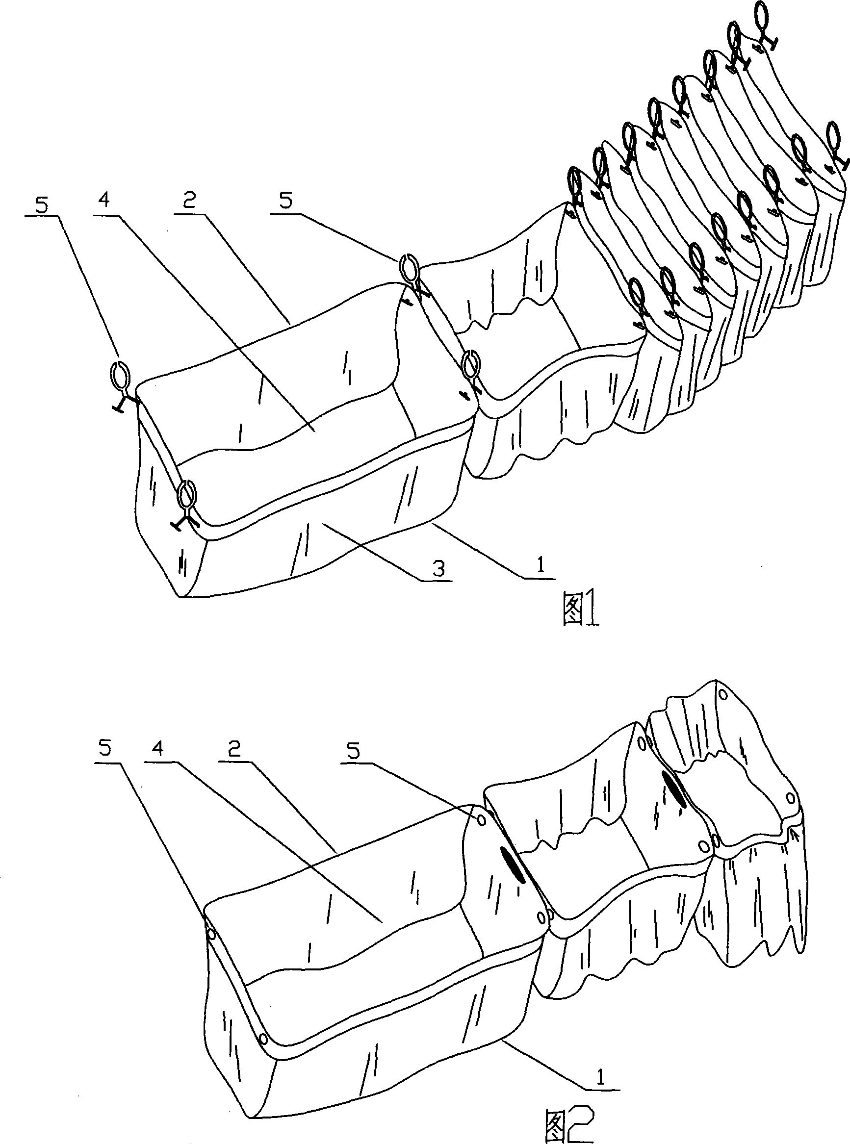
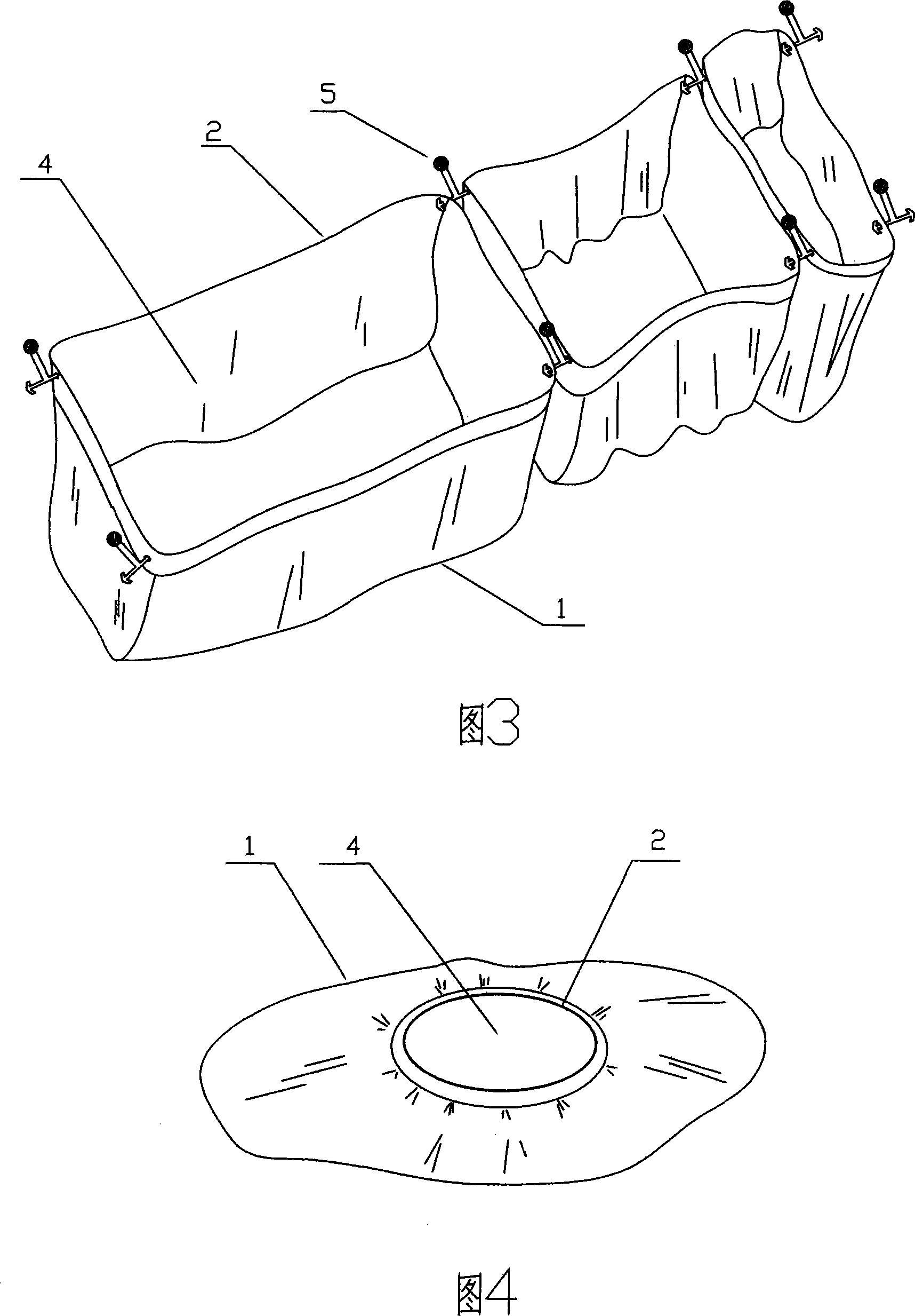
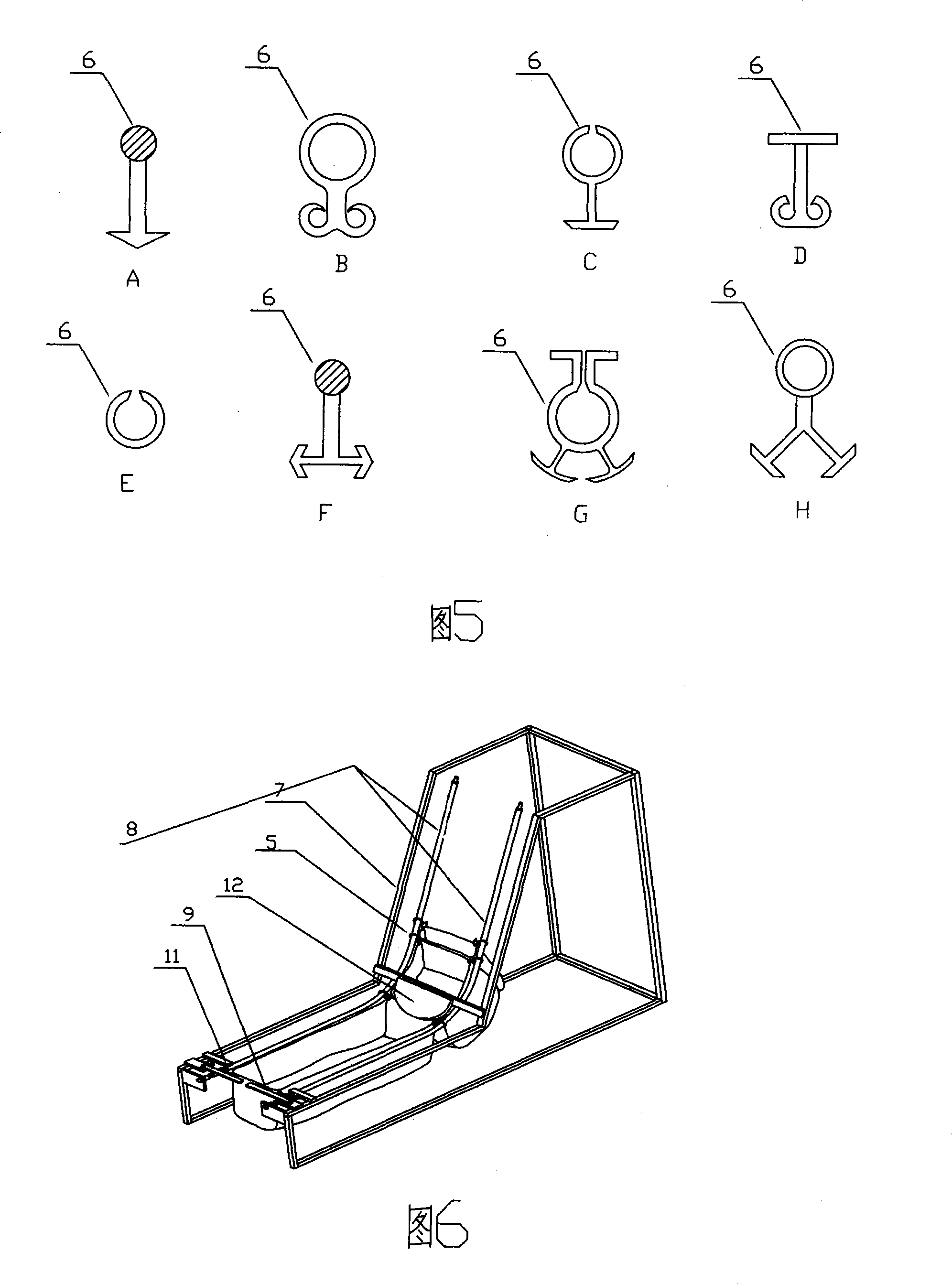
[0029] As shown in Figure 6 and Figure 9, the shoe cover body 3 is slidably fixed on the shaft-shaped shoe cover feeding guide rail 8 of the automatic shoe cover machine through the open ring shoe cover sliding connector 5, and the first shoe cover is pre-drawn to the feeding guide rail 8 At the exit of the frame 7 at the front end, and the slide connector 5 on it is pulled past the position of the first stopper 11, and its tail is positioned behind the second stopper 12, because the stopper 11 and the first stopper Two stoppers 12 are baffle plates made of elastic materials, which have certain resistance and are sufficient to overcome the pulling force of the shoe cover rubber pulled apart, so the shoe cover can be kept in an open state for use, and the pin is put into the In the shoe cover bag-shaped opening 4 that is pulled open, then the pin is dragged out from the front end outlet of the frame 7 along the shoe cover feeding guide rail 8 parallel to the rear, and now the sl...

Embodiment 2

[0031] As shown in Figure 7 and Figure 10, its working process is roughly the same as that of Embodiment 1, the difference is that there is no additional sliding connector for the shoe cover in series, and the sliding connector 5 is the perforation on the shoe cover body 3, and the shoe cover The connection with the shoe cover is set on the shoe cover feeding shaft-shaped guide rail 8 through its perforation, the linkage swing arm 9 is a single-piece swing arm structure, and the first stopper 11 and the second stopper 12 are both hinged. The set single pendulum structure, the second stopper 12 is connected with the linkage swing arm 9 through the transmission rod 13, the shoe cover is out of the series state and the follow-up shoe cover remains open, which no longer overcomes the second stopper 12 The resistance of the elastic baffle is realized by the linkage of the swing arm 9 and the linkage of the second stopper 12 to flip release and return blocking.

Embodiment 3

[0033] As shown in Figure 8 and Figure 11, its working process is the same as that of Embodiment 1, the difference is that: ①The frame 7 is a horizontal structure, ②The shoe cover feeding guide rail 8 is a chute-shaped structure, ③The shoe cover is slidingly connected The sliding and fixing part 6 of the piece 5 is in the shape of a hanging bead, and ④ the first stopper 11 is a single pendulum structural member hinged.


PUM


Abstract

The invention relates to a tandem type shoe cover for machine service, which comprises a plurality of bag-shaped shoe cover bodies (3) made from flexible material (1) and elastic material (2); a bag-shaped opening (4) of each shoe cover body (3) is provided with a sliding connection devices (5) matched with a material feeding guide rail and a plurality of shoe cover bodies (3) are mutually connected with each other in series orderly to form a consistent monolithic construction. The shoe cover overcomes the defects of low output, high failure rate, etc., for the prior shoe cover dispensers and is a tandem type shoe cover for machine service that is used in combination with dragging automatic shoe cover dispensers.

Description

technical field [0001] The invention relates to a tandem machine shoe cover used on an automatic shoe cover machine. Background technique [0002] In order to solve the problem of people entering the house and changing shoes to keep the indoor environment hygienic, I first invented the first-generation utility model automatic shoe cover machine in 2000 and launched it on the market, the patent number is 00255972.2, and then developed two large-capacity automatic shoe cover machines, And all of them have been approved for patent and listed, patent number 200320125454.9 and 200520096276.0. After a long period of market use information feedback, the above-mentioned automatic shoe cover machines all have a common problem: that is, the production rate is unstable and cannot be guaranteed to be 100%. The reason is that the machine shoe covers used in conjunction with the prior art automatic shoe cover machines have too high a quality requirement. Because each of the current machin...

Claims


Application Information

Patent Timeline
Patent Type & Authority Applications(China)
IPC IPC(8): A43B3/16A47G25/80
Inventor 徐良杰
Owner 徐良杰
Why Eureka
Try Eureka