Double rubberbands four sliding rails arrow type ejection mechanism

A slide rail and rubber band technology is applied in the field of mechanical launchers, which can solve the problems of narrow application fields, limited application scope, and inability to adjust the position of objects to be launched.

Inactive Publication Date: 2008-08-06
HARBIN ENG UNIV
View PDF1 Cites 8 Cited by
  • Summary
  • Abstract
  • Description
  • Claims
  • Application Information

AI Technical Summary

Problems solved by technology

The design idea of ​​the mechanical object ejection mechanism comes from the traditional ejection method, that is, the energy storage trigger type. There is still relatively little research on related technologies in China. The typical one is "Three Rubber Band Rail Barrel Type Launching Mechanism" (patent application number: 200610150950.8) , this scheme is based on the principle of barrel-type launch, which can only launch small spherical objects with simple shapes, and the weight of the launch object is relatively light. When the way the object to be launched is placed in the source area is different from the position required for pre-launch, it cannot be adjusted. The position of the object, which greatly limits its scope of application, the application field is relatively narrow

Method used


Image

  • Double rubberbands four sliding rails arrow type ejection mechanism
  • Double rubberbands four sliding rails arrow type ejection mechanism

Examples


Embodiment Construction

[0027] The present invention is described in more detail below in conjunction with accompanying drawing example:

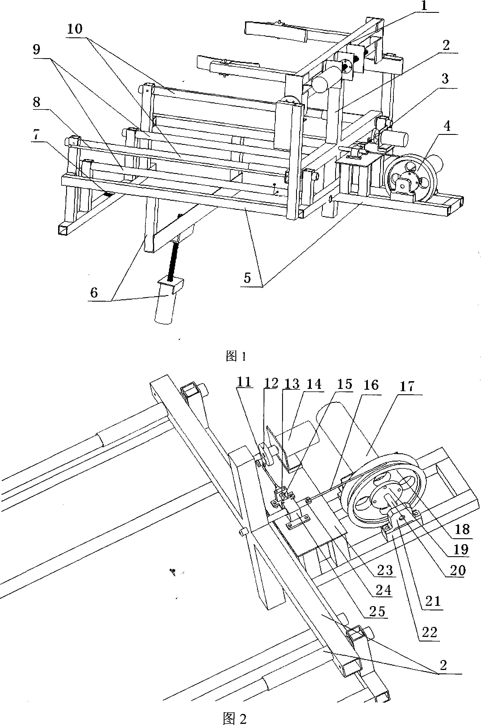
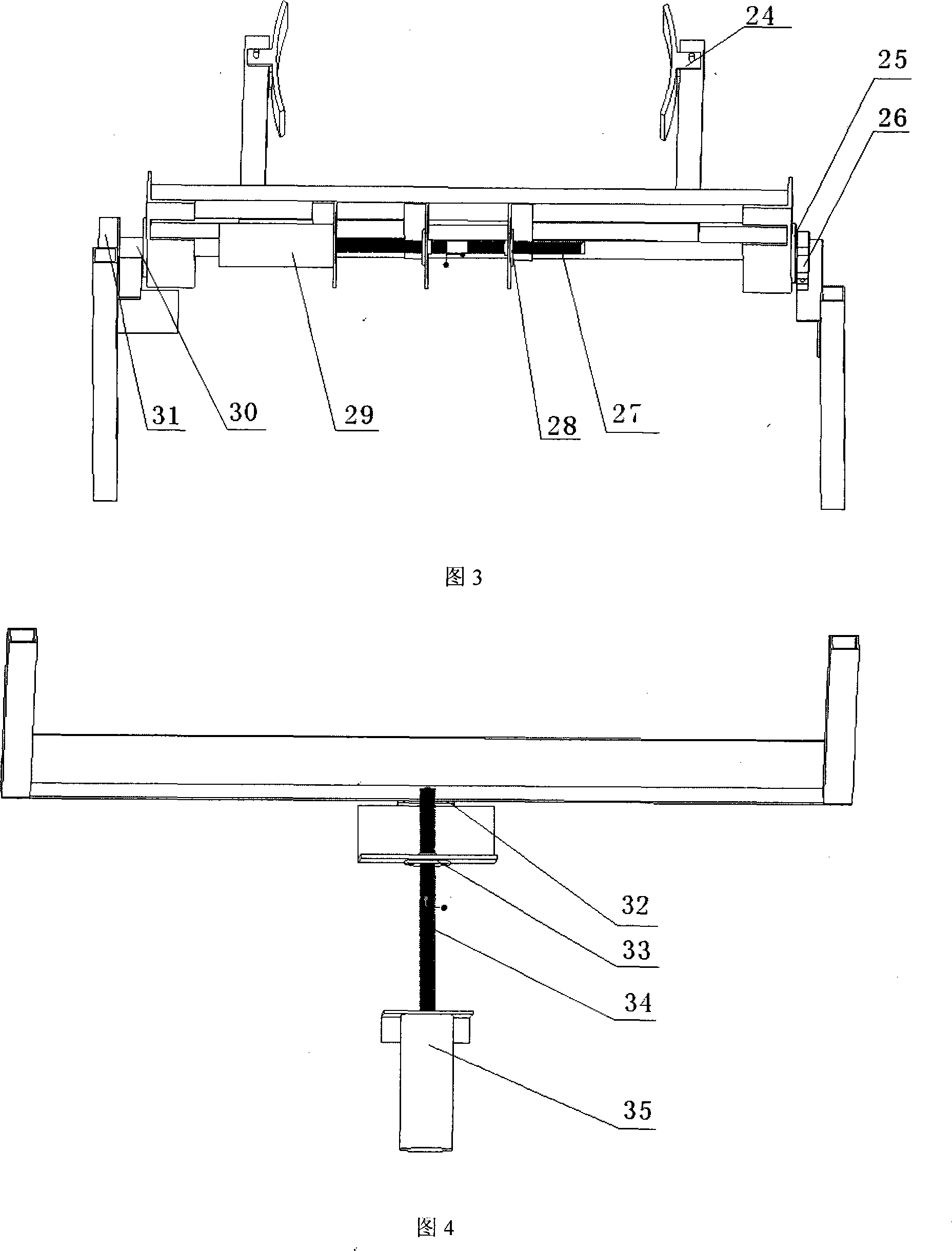
[0028] The present invention includes a frame 5 , a launch rail 10 , a launch track 9 , an angle adjustment device 6 , a trigger device 3 , a wire take-up and release device 4 and an overturning manipulator 1 . Wherein the winding wheel 18 is connected to the bearing seat 21 through the shaft coupling 20, one end is connected to the winding motor 17, fixed on the frame 5, and the axis is parallel to the frame by adjusting the height of the cushion block 22; the trigger device 3 The motor 14 is fixed on the support plate 23 through angle aluminum, the support plate 23 is connected with the frame 5 through 4 aluminum alloy square tubes, the pin pulling motor 14 drives the cam mechanism 12 to pull the steel wire 13, and the other end of the steel wire 13 is connected to the bayonet pin 15 connected; the manipulator 1 needs to realize two degrees of freedom of graspin...


PUM


Abstract

The invention provides an ejection mechanism of bow type with two rubber bands and four slides, essentially comprising a chassis 5, an orbit of an ejection cabin base 10, an ejection orbit 9, an angel adjusting device 6, a triggering device 3, a line withdrawing and setting device 4 and a turning manipulator 1. A line rolling motor 17 passes through a line rolling wheel 18 through a coupling 20; the other side uses a screw to connect an end cover 19 and the lien rolling wheel into a whole through a bolt; the other end of the coupling is fixed on a bearing block 21; an end of a pin 24 is provided with a screw thread and is connected with an ejection cabin base 2; the other end of the pin 24 is connected with a steel wire 15; the other end of the ejection cabin base is connected with a front end on the chassis through two rubber bands 8; a motor 14 is connected with a cam structure 12 and is fixed on a support board 23; a manipulator 1 is fixed at a corresponding position on the chassis 5 through two aluminum rods; an aiming device 7 is fixed on a centre line at the front end of the chassis. The mechanism of the invention can eject various shapes, automatically grab objects, present positioning of high precision, have the function of instant triggering of elastic potential energy, and be reused.

Description

(1) Technical field [0001] The invention relates to a robot structure, in particular to a mechanical launching device. (2) Background technology [0002] With the continuous change of modern industrial operating conditions, more and more methods of non-contact conveying objects are involved, so it has become a trend to design an ejection mechanism that can adapt to various working conditions. The design idea of ​​the mechanical object ejection mechanism comes from the traditional ejection method, that is, the energy storage trigger type. There is still relatively little research on related technologies in China. The typical one is "Three Rubber Band Rail Barrel Type Launching Mechanism" (patent application number: 200610150950.8) , this scheme is based on the principle of barrel-type launch, which can only launch small spherical objects with simple shapes, and the weight of the launch object is relatively light. When the way the object to be launched is placed in the source ...

Claims


Application Information

Patent Timeline
Patent Type & Authority Applications(China)
IPC IPC(8): B65G31/00B25J3/00
Inventor 陈东良李林李建朋万晓正穆星科林秋红周小英杜平于贵芙刘晶晶
Owner HARBIN ENG UNIV
Why Eureka
Try Eureka