Cabling structure

A wiring structure and transmission line technology, applied in the direction of coupling devices, electrical components, circuits, etc., can solve the problems of cable thickness, quantity, signal transmission constraints, technical structure complexity, etc., to save engineering time, reduce engineering costs, and discharge cloth easy effect

Inactive Publication Date: 2008-08-06
NANO CHEM TECH SUZHOUCO
View PDF0 Cites 9 Cited by
  • Summary
  • Abstract
  • Description
  • Claims
  • Application Information

AI Technical Summary

Problems solved by technology

[0003] However, the above-mentioned technical structure is too complicated, and the method of covering the lead-in channel and organizing various cables in the lead-in channel is adopted. Therefore, according to the width and height restrictions of the lead-in channel, there are differences in the thickness, quantity, and size of various cables. Constrained issues such as signal transmission

Method used


Image

  • Cabling structure
  • Cabling structure
  • Cabling structure

Examples


Embodiment Construction

[0056] Hereinafter, possible embodiments according to the present invention will be described in detail with reference to the accompanying drawings.

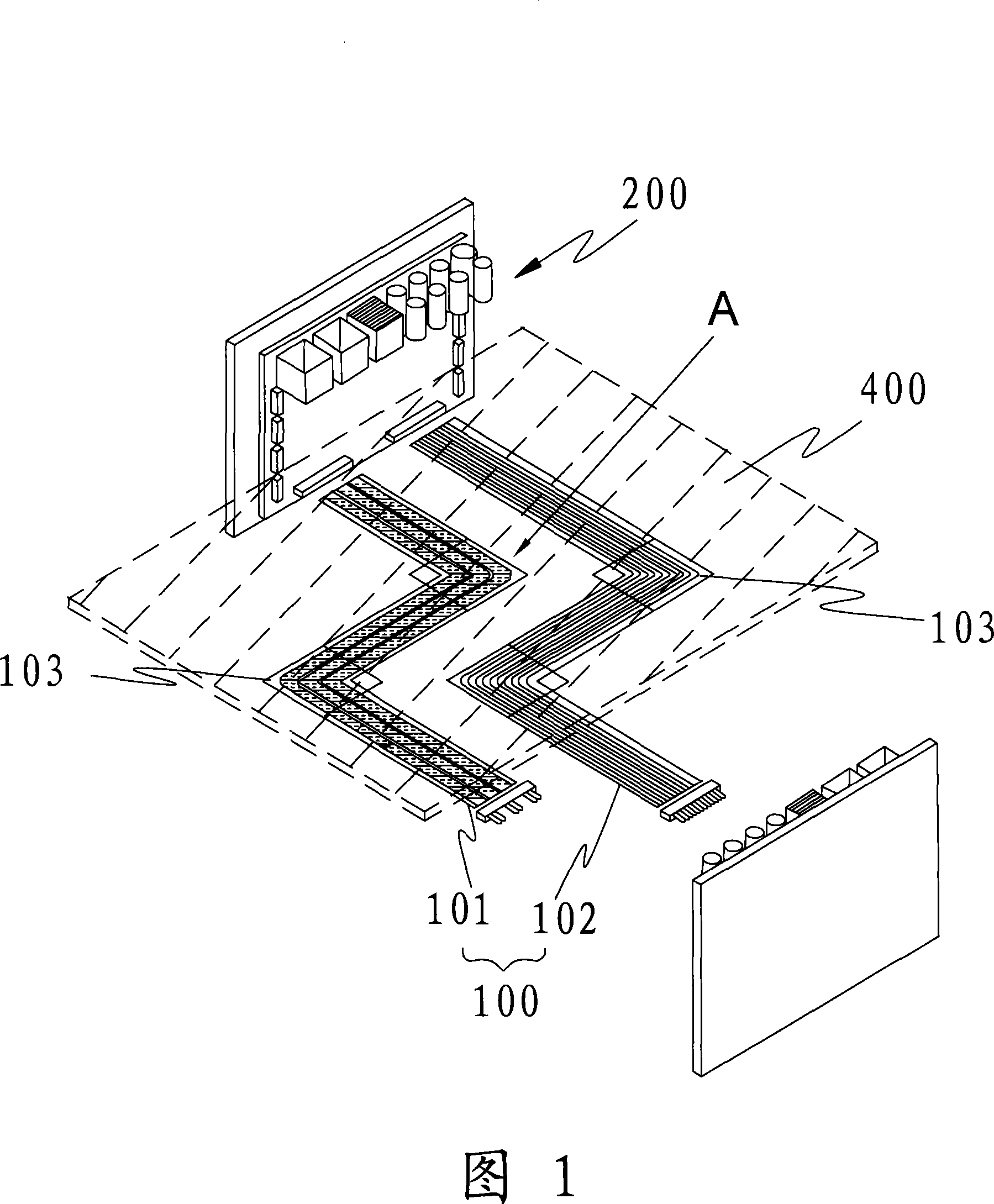
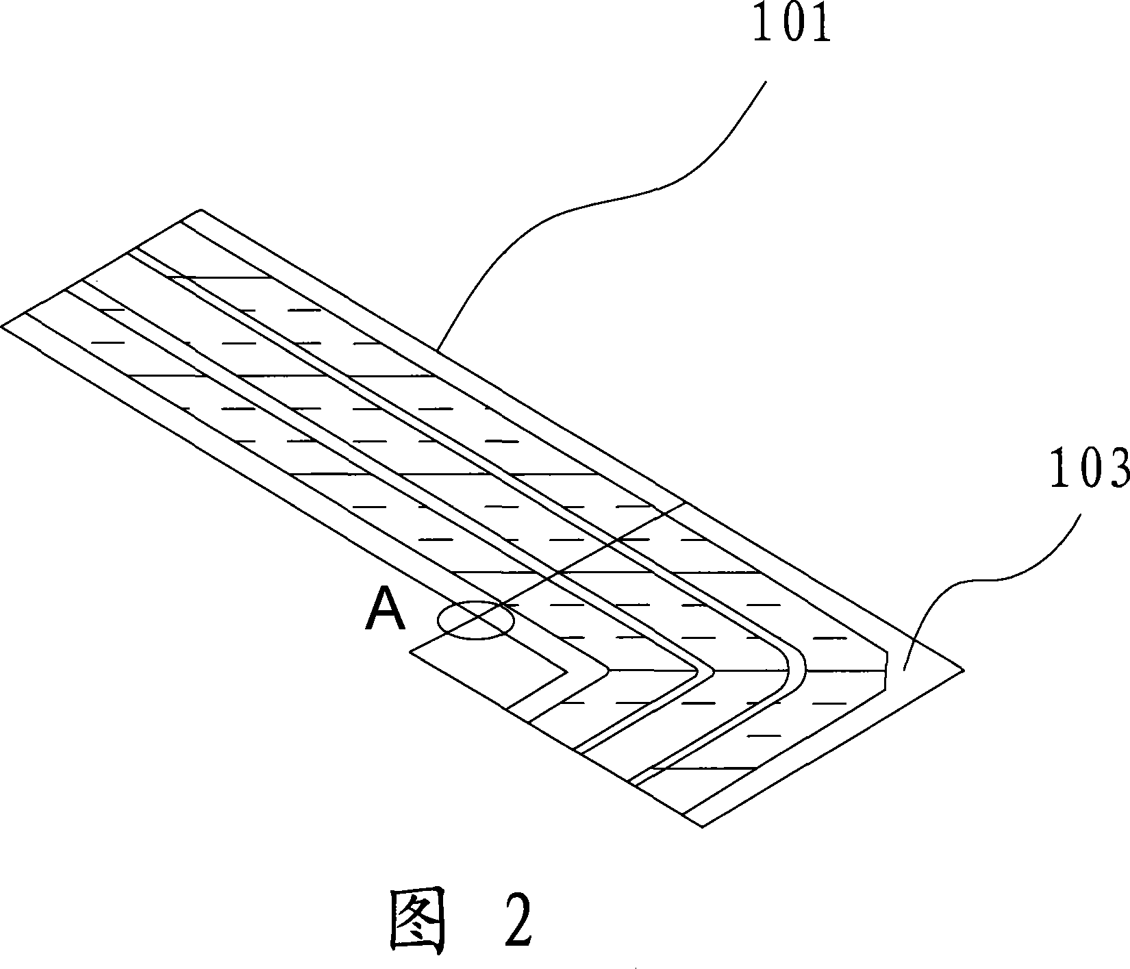
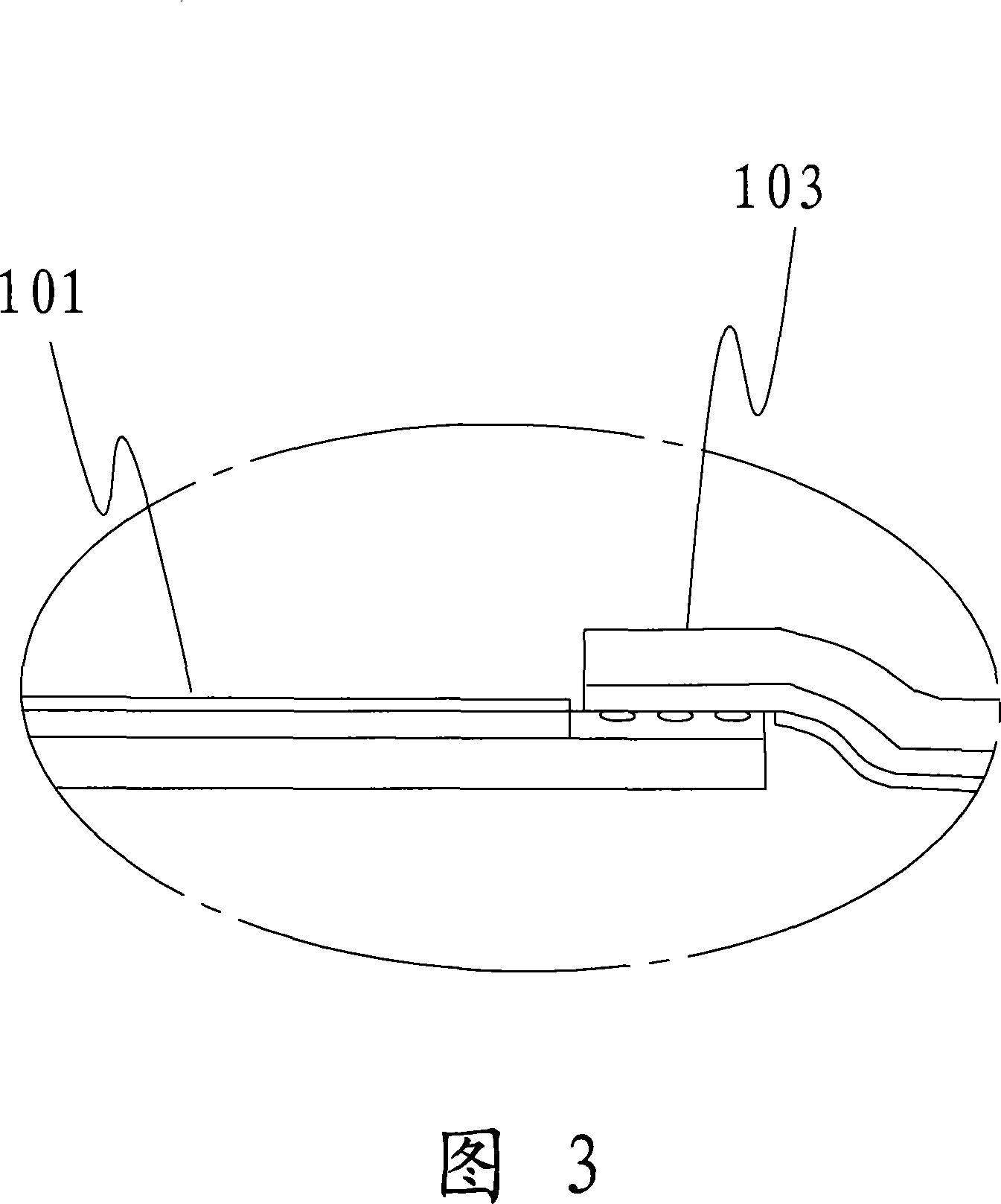
[0057] Fig. 1 is a structural diagram of a wiring system laid by ground material according to an embodiment of the present invention, which is installed on the bottom of the ground material 400, and the F-PCB transmission line 100 for transmitting signals is connected to the F-PCB transmission line 100. It is formed by multiple connection devices 200 connected with external electrical machines. F-PCB is the general abbreviation of flexible circuit board in the industry. The F-PCB transmission line 100 in the drawings of the present invention is a kind of laying transmission line flexible printed circuit board structure.

[0058] More specifically, the above-mentioned F-PCB transmission line 100 is divided into an F-PCB high-frequency transmission line 101 and an F-PCB differential transmission line 102, which are used for EMI (e...


PUM


Abstract

The invention provides a wiring mechanism, comprising a flexible circuit board for transmitting a signal and a plurality of connection devices for connecting the flexible circuit board with external appliances, wherein, the flexible circuit board for transmitting the signal is arranged on the bottom of a parent material. As is explained in the former part, the invention provides the wiring connection structure between various complicated and separated appliances in a house or a building environment. Various appliances are connected to the connection devices by adopting the transmission line of the flexible circuit board arranged on the lower side of the parent material in a way that the flexible circuit board is connected with a plurality of connection devices to replace the cables connected with the wiring tube inside the wall surface and the building. Therefore, the wiring is very convenient, the engineering time is saved, the engineering fee is reduced, the additional decorating space is not occupied and the decorating environment is not limited.

Description

technical field [0001] The invention relates to a wiring structure for connecting lines between electrical appliances, mainly referring to the wiring connection structure between various machines that require a certain installation distance in building environments such as houses. Background technique [0002] In the prior art, the connecting lines of household appliances are arranged in such a way that various cables are arranged through walls and wiring pipes inside buildings, such as the wiring matrix structure of Korean Utility Model Application No. 20-2005-0023672 The related technology of the present invention provides a substrate for wiring formed by integral injection molding of plasticized wood materials. The substrate is located at the bottom, and it forms an outer casing with a plurality of cover plates, and the upper end of the substrate uses multiple support plates to form multiple introduction channels. Cover each channel with a cover ...

Claims


Application Information

Patent Timeline
IPC IPC(8): H02G3/36H01R11/11H01R12/24H05K1/00H05K1/11H01R12/77
Inventor 白云弼张宽植栾万强
Owner NANO CHEM TECH SUZHOUCO
Why Eureka
Try Eureka