Unmanned helicopter

An unmanned helicopter and fuselage technology, which is applied to unmanned aircraft, rotorcraft, motor vehicles, etc., can solve the problem of insufficient cooling of the engine, and achieve the effect of small space, improved cooling performance, and improved cooling performance.

Inactive Publication Date: 2008-08-06
YAMAHA MOTOR CO LTD
View PDF3 Cites 53 Cited by
  • Summary
  • Abstract
  • Description
  • Claims
  • Application Information

AI Technical Summary

Problems solved by technology

As a result, the engines cannot be cooled sufficiently when conducting such flights

Method used


Image

  • Unmanned helicopter
  • Unmanned helicopter
  • Unmanned helicopter

Examples


no. 1 example

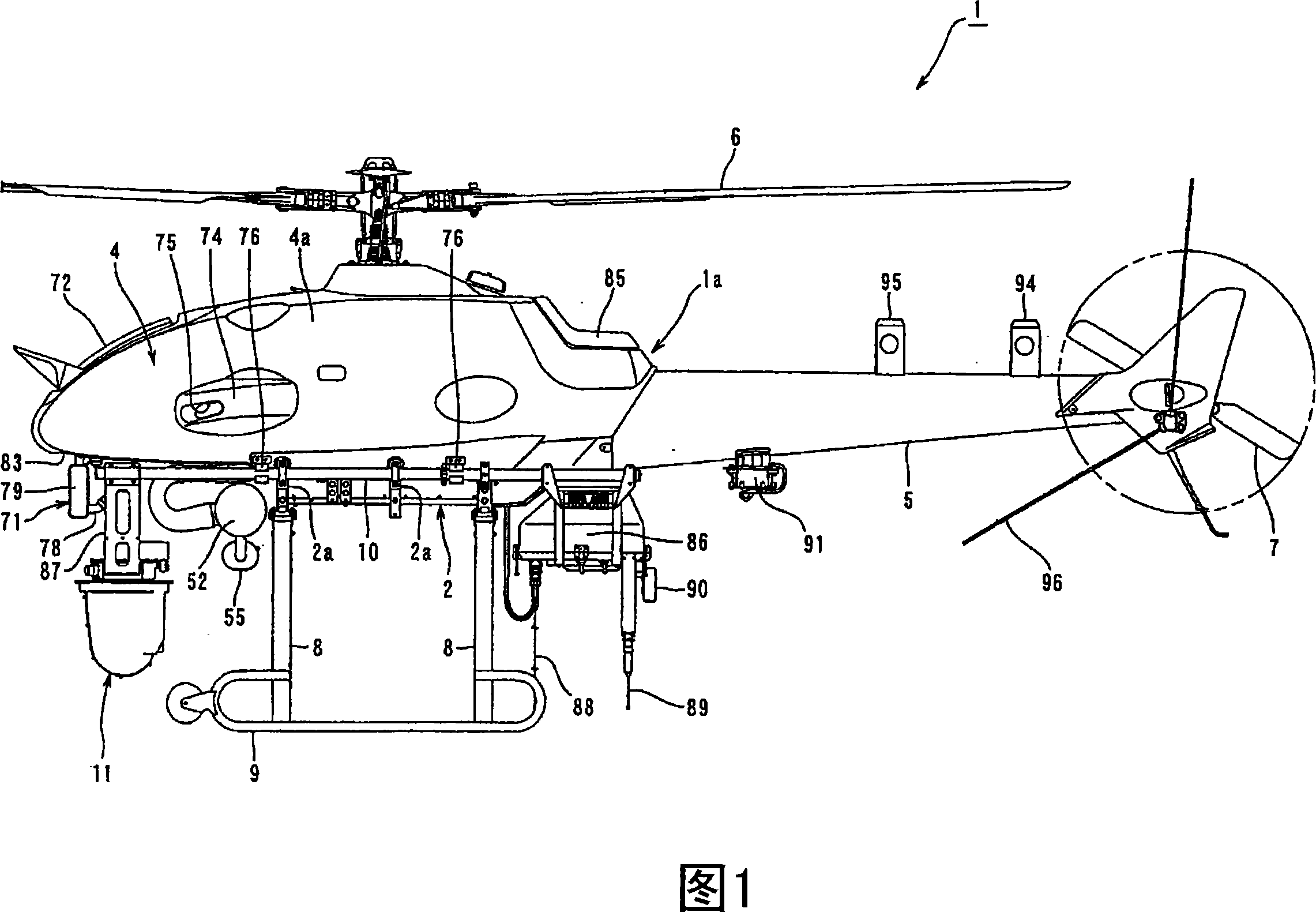
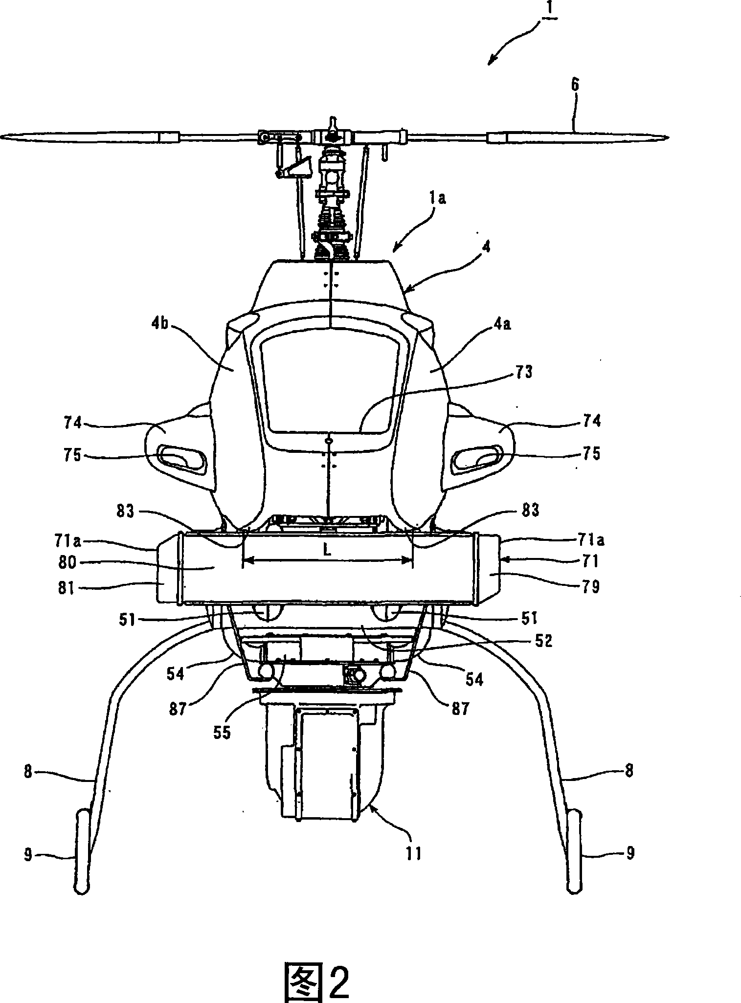
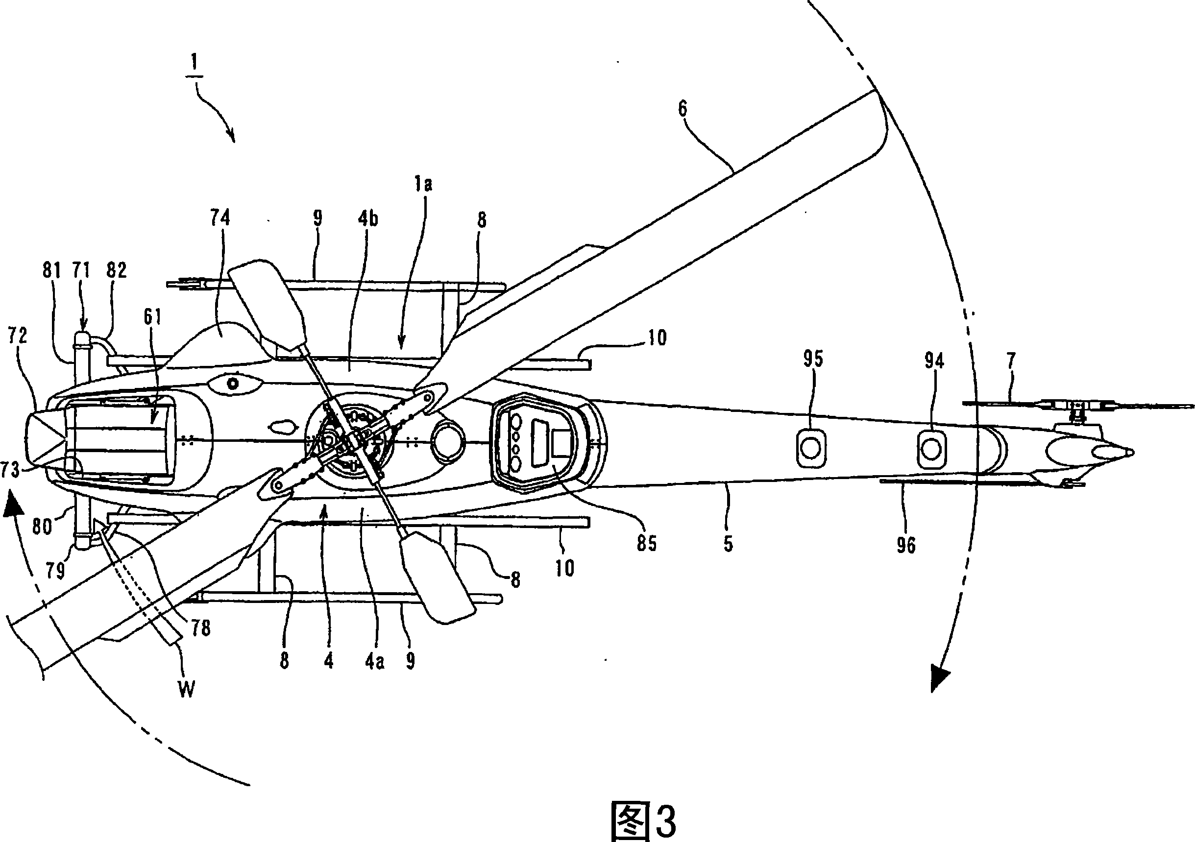
[0028] Embodiments of the unmanned helicopter according to the present invention will be described in detail below with reference to FIGS. 1 to 5 .

[0029] The unmanned helicopter 1 according to the present embodiment has a fuselage 1a including a body frame 2 described below (see FIGS. 4 and 5 ), a power unit 3 mounted on the body frame 2, covering the body frame 2 except the bottom The main body 4 (see FIGS. 1 to 3 ) outside the area of ​​the periphery and the tail body 5 connected to the rear end of the body frame 2 . The main rotor 6 is arranged on the upper part of the main body 4 , and the tail rotor 7 is arranged on the rear part of the tail body 5 .

[0030] As shown in FIGS. 4 and 5 , the body frame 2 is formed in the shape of a hollow box extending along the longitudinal direction of the unmanned helicopter 1 . A pair of support legs 8 arranged in the longitudinal direction of the body 1 a are fixed to the lower end of the body 2 . Support legs 8 are formed to ext...

no. 2 example

[0069] The unmanned helicopter according to the present invention can be constructed as shown in FIGS. 6 to 8 . In these drawings, the same or equivalent members as those already described with reference to FIGS. 1 to 5 are given the same reference numerals or symbols, and detailed descriptions thereof are appropriately omitted.

[0070] In the helicopter 1 according to the present embodiment, the second radiator 71 is formed in a vertically elongated shape that is longer in the vertical direction, and is provided at a position below the main body 4 on the left side of the fuselage 1a. The second radiator 71 shown in the second embodiment constitutes the radiator described in claim 3 of the present invention. As shown in FIGS. 7 and 8 , the second radiator 71 according to the present embodiment is mounted to the load bar 10 located on the left side of the fuselage through a bracket 10 a.

[0071] Specifically, as shown in FIG. 6, the second radiator 71 according to the presen...


PUM


Abstract

An unmanned helicopter has a fuselage (1a) with a main body (4) and a tail body; a main rotor (6) provided above the main body (4) and driven by an engine in the fuselage (1a); a tail rotor placed at the rear of the tail body (5); a pair of left and right support legs (8,8) extended downward from lower left and lower right sections of the main body (4); a pair of left and right skids (9) provided at lower ends of the support legs (8,8) and positioned, in a front view, more on the outside in the width direction of the fuselage (1a) than the main body (4); and a radiator (71) positioned, in a side view, more on the front side than the front edges of the skids (8) and formed so as to extend downward from the vicinity of a bottom surface (83) of a main body front section so that an airflow receiving surface of the radiator is oriented in the front-rear direction of the fuselage (1a). Outer edges, in the width direction of the fuselage (1a), of the radiator (71) are projected outward, in the front view, from outer edges of a main body bottom surface (83) near the radiator (71). Also, outer edges (71a) of the radiator (71) are positioned more on the inside, in the width direction of the fuselage (1a), than the skids (9).

Description

technical field [0001] The invention relates to an unmanned helicopter with a radiator. Background technique [0002] Conventionally, for an unmanned helicopter controlled by remote control performed by an operator observing the fuselage, it is used to spread pesticides from the air or take aerial images, videos, and the like. In recent years unmanned helicopters can fly out of the operator's field of vision by utilizing GPS. As a result, unmanned helicopters of this type can take images of places that are inaccessible to manned helicopters, such as volcanoes and disaster sites, and actually play an active role in such places. For example, an unmanned helicopter for spreading chemicals such as pesticides is disclosed in JP-A-2002-166893, and an unmanned helicopter for taking aerial images and the like is disclosed in JP-A-2002-293298 . [0003] Conventional unmanned helicopters are provided with radiators directed obliquely forward and upward in the frontmost part of the ...

Claims


Application Information

Patent Timeline
Patent Type & Authority Applications(China)
IPC IPC(8): B64D33/10A01C7/08A01M7/00B64C27/06
CPCB64C2201/024B64C2201/044B64C2201/127B64C2201/108B64C39/024B64U50/11B64U2101/30B64U10/17B64U60/50B64U80/80B64C27/06A01M7/00A01C7/08B64U10/10B64U30/20
Inventor 坂本修平见育彦中山浩典
Owner YAMAHA MOTOR CO LTD
Why Eureka
Try Eureka