
System for cluster managing in the Ethernet switch layer and the method thereof

A technology of cluster management and switches, which is applied in the management system field of Ethernet switches, can solve the problems of limited number of devices, inability to realize automatic discovery of switch topology, and inability to discover VLAN devices, etc., so as to prevent cheating of illegal devices and meet management requirements , the effect of reducing the burden

Active Publication Date: 2010-08-18
ZTE CORP
View PDF5 Cites 0 Cited by
  • Summary
  • Abstract
  • Description
  • Claims
  • Application Information

AI Technical Summary

Problems solved by technology

However, the devices discovered by the topology can only be limited to the default VLAN without VLAN tags, and cannot discover devices in any specified VLAN, so that subsequent cluster management functions cannot be completed, which brings great challenges to actual networking applications. Due to the limitations of the network, it cannot meet the management needs of telecom operators; secondly, the number of devices that can be managed by command devices is limited, it is impossible to increase without limit, and it is impossible to realize the hierarchical management needs of large-scale networking; device discovery lacks An effective security authentication mechanism cannot prevent spoofing of illegal devices
[0008] U.S. Patent No. 6,725,264 discloses a "equipment and method for redistribution of network processing information in cluster network equipment", which only realizes the method of managing a single cluster, and does not realize that switches have different roles in different clusters, and cannot Realize hierarchical management of clusters
U.S. Patent No. 6,636,499 discloses a "device and method for cluster network device discovery". The switch topology discovery of this patent is a process that needs to be manually determined step by step to join the cluster, and then obtain the next-hop switch neighbor device information table, and establish The process of a complete switch topology; this patent realizes the discovery of neighbor devices, but to obtain a complete switch topology requires the discovered switch (ie, a candidate switch) to join the cluster and initiate a topology request with the support of the command machine, which cannot be realized in When the discovered switch (that is, an independent switch) does not join the cluster, it can automatically discover the complete switch topology structure, and it cannot realize the automatic discovery of the peripheral switch topology structure when the intermediate switch joins the non-command switch cluster, and cannot obtain it on the non-command switch Complete switch topology, the invention does not mention how to discover the topology in different VLANs

Method used


Image

  • System for cluster managing in the Ethernet switch layer and the method thereof
  • System for cluster managing in the Ethernet switch layer and the method thereof
  • System for cluster managing in the Ethernet switch layer and the method thereof

Examples


Embodiment Construction

[0037] The core content of the present invention will be further described in detail below in conjunction with the accompanying drawings.

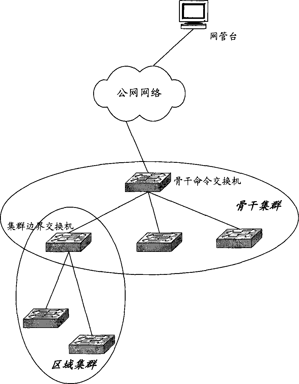
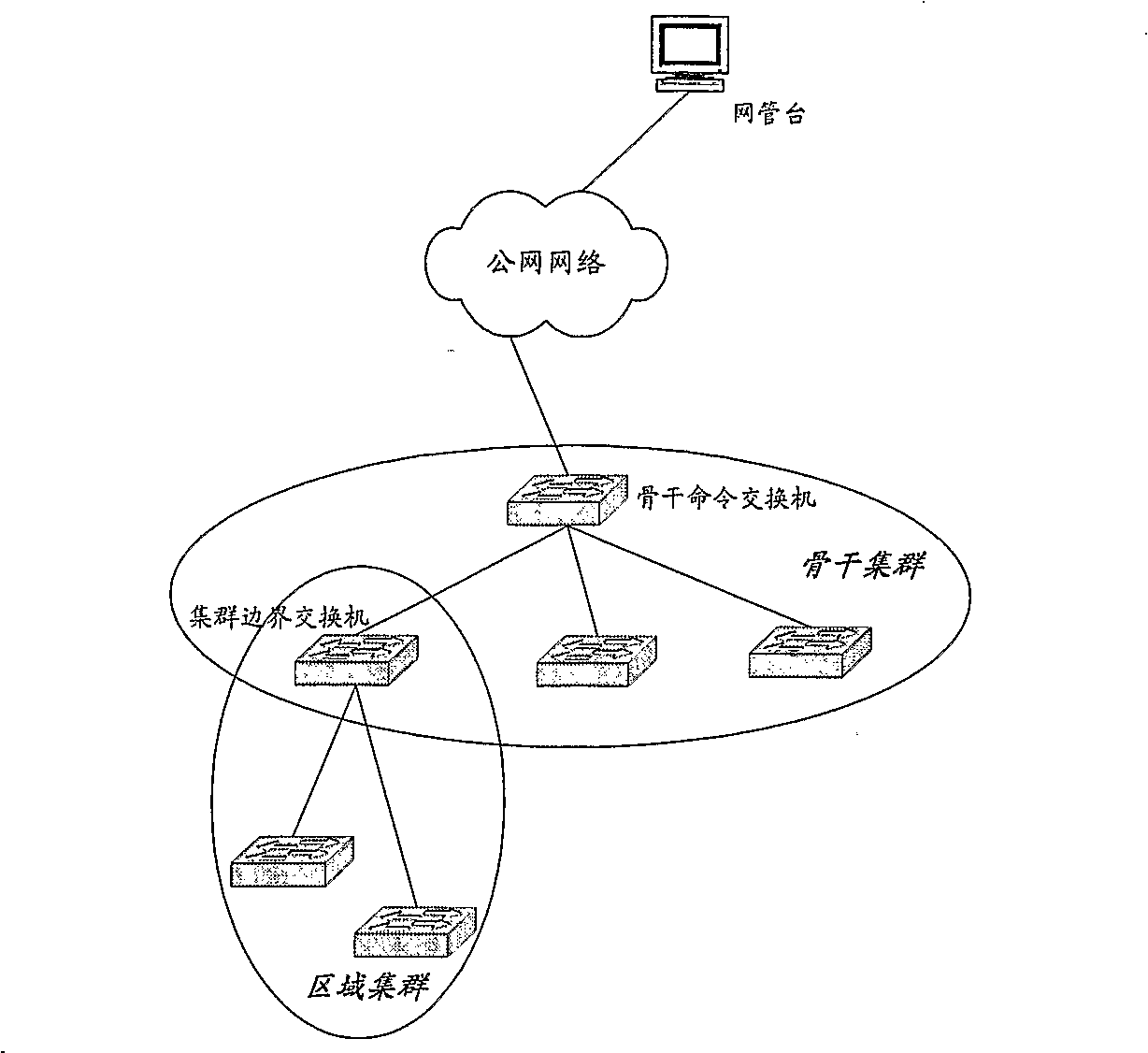
[0038] In the hierarchical cluster management system of Ethernet switches provided by the present invention, the cluster is composed of multiple Ethernet switches in the same broadcast domain (i.e. the same VLAN), wherein the management switch is called a command switch, and the other managed The unique switch of the cluster is called a member switch, and the unique identification of the cluster consists of two parts: the device physical address (MAC address) of the command switch of the cluster and the VLAN in which the cluster is located. Fig. 1 is a typical network diagram of cluster management based on the present invention. As shown in Figure 1, the cluster that provides a public network IP address and a management interface is called a backbone cluster, the command switch of the backbone cluster is called a backbone command switch, a...


PUM


Abstract

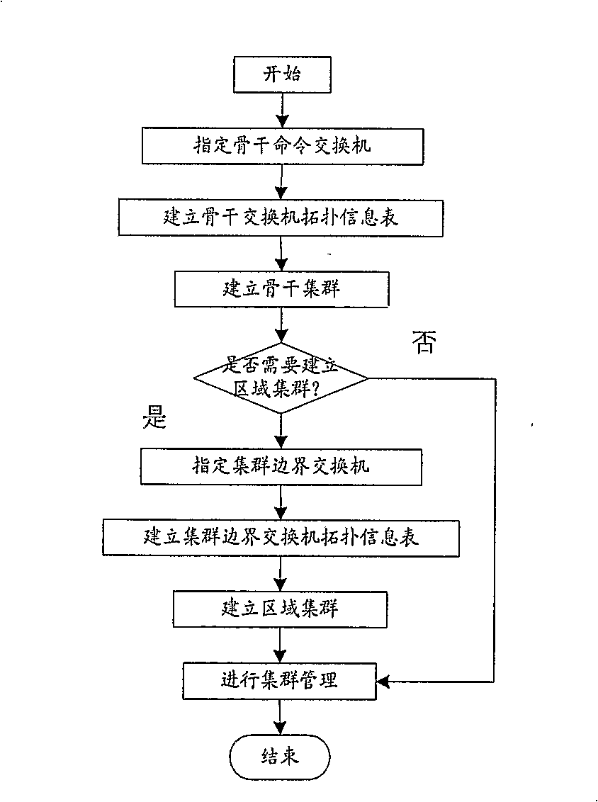
A system for cluster managing in the ethernet switch layer and the method thereof, wherein, NDP protocol module, TDP protocol module and GMP protocol module are added to the switch protocol stack, the topology table of different devices are established according to the said NDP protocol module and TDP protocol module in different VLAN so as to the cluster are established in any designated VLAN toimplement the layer management and the redundancy management of the cluster.

Description

technical field [0001] The present invention relates to a management system and method of an Ethernet switch, in particular to a hierarchical cluster management system and method based on a virtual local area network (Virtual Local Area Network) (hereinafter referred to as VLAN). Background technique [0002] In the current data network environment, switch management methods are mainly divided into three types: local management method (using serial port), remote management method (using network port, through Simple Network Management Protocol (SNMP protocol for short) or Telnet protocol) and cluster management. [0003] For the local management mode, it only needs to be directly connected to the management platform through the serial port, the management method is relatively simple, and there is no need to configure the corresponding Internet Protocol (Internet Protocol) (hereinafter referred to as IP) address for the switch, saving valuable IP address resources. Its disadv...

Claims


Application Information

Patent Timeline
IPC IPC(8): H04L12/56
CPCH04L49/351H04L49/354H04L45/46
Inventor 曲延锋魏月华赵志强胡鹏范成法
Owner ZTE CORP
Learn More