Liquid heating container

A liquid heating container and liquid technology, which is applied to electric heating devices, cooking utensils, multi-unit cooking utensils, etc., can solve the problems of no liquid covering and dry burning, and achieve the effects of long service life, prevention of dry burning, and reasonable design.

Inactive Publication Date: 2008-08-13
佛山市顺德区康迈斯电器有限公司
View PDF2 Cites 4 Cited by
  • Summary
  • Abstract
  • Description
  • Claims
  • Application Information

AI Technical Summary

Problems solved by technology

But when this structure has less water in the container, if the electric heating container (such as electric kettle, etc.) tilts a small angle (for example 5 degrees) to a certain direction, there may be liquid covering on the bottom surface of the container, and If there is no liquid covering other places on the bottom of the container, dry burning will also occur on the bottom without liquid covering; for the above problems, Chinese Patent Application No. 95194418.5 discloses a kind of spacer at the bottom of the container. Action bimetal (or other trigger device), this scheme solves the above problems to a certain extent, but it has not completely solved the problem of dry burning when the container is tilted. When the connection direction of the two metal sheets is vertical, the inner side of the bottom of the pot that is in contact with the two metal sheets is covered with liquid, while the inner side of part of the bottom surface of the pot is not covered by liquid. At this time, the part that is not covered by the liquid will also appear dry burning

Method used


Image

  • Liquid heating container
  • Liquid heating container
  • Liquid heating container

Examples


Embodiment

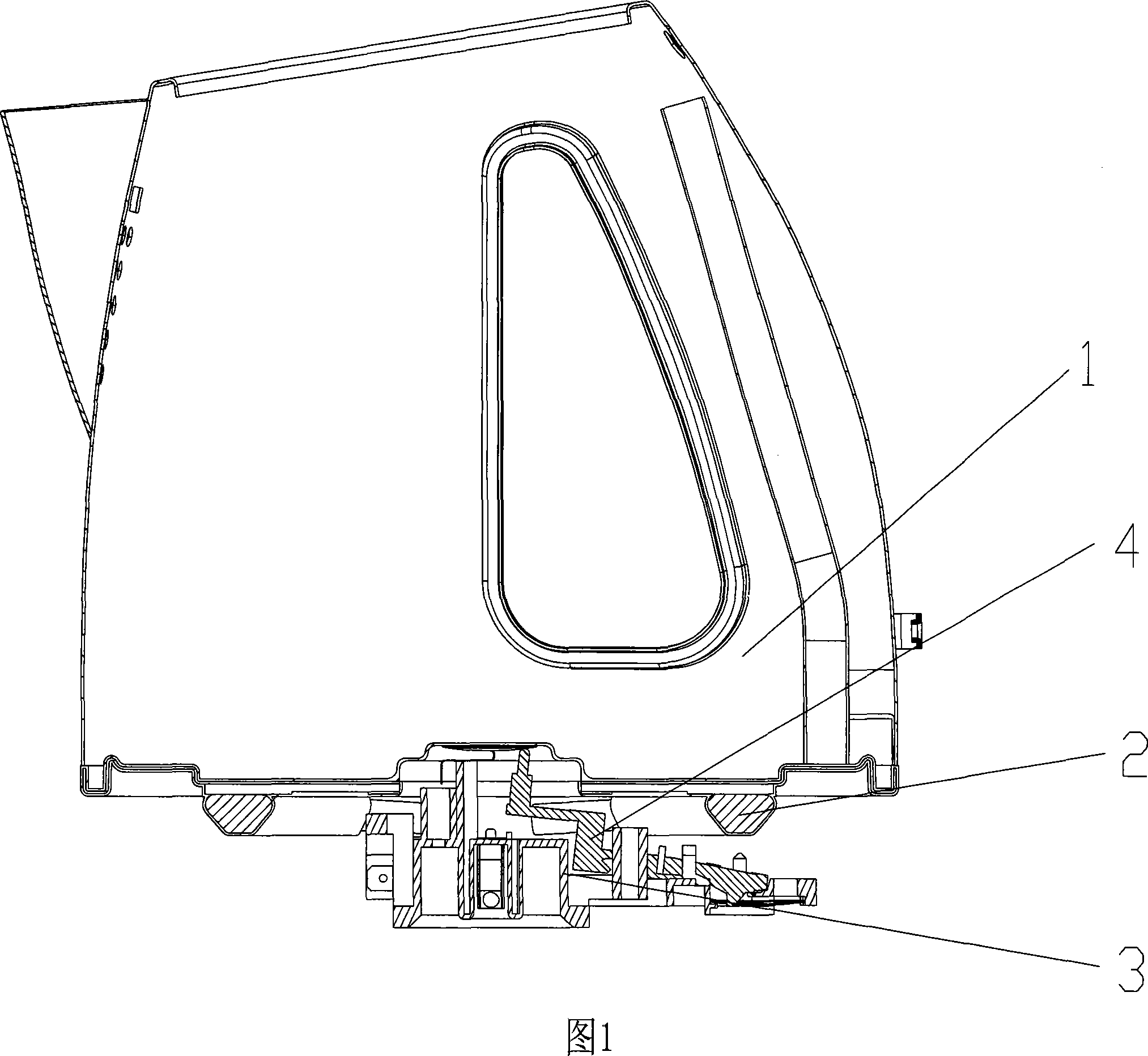
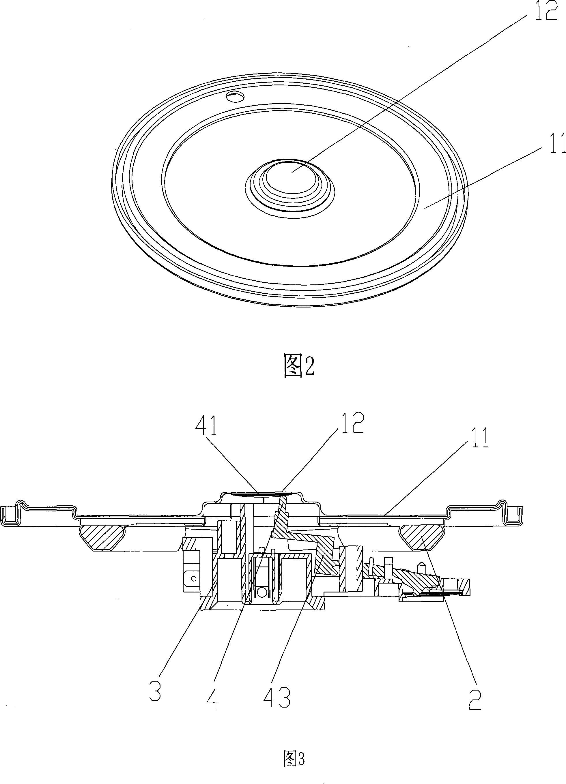
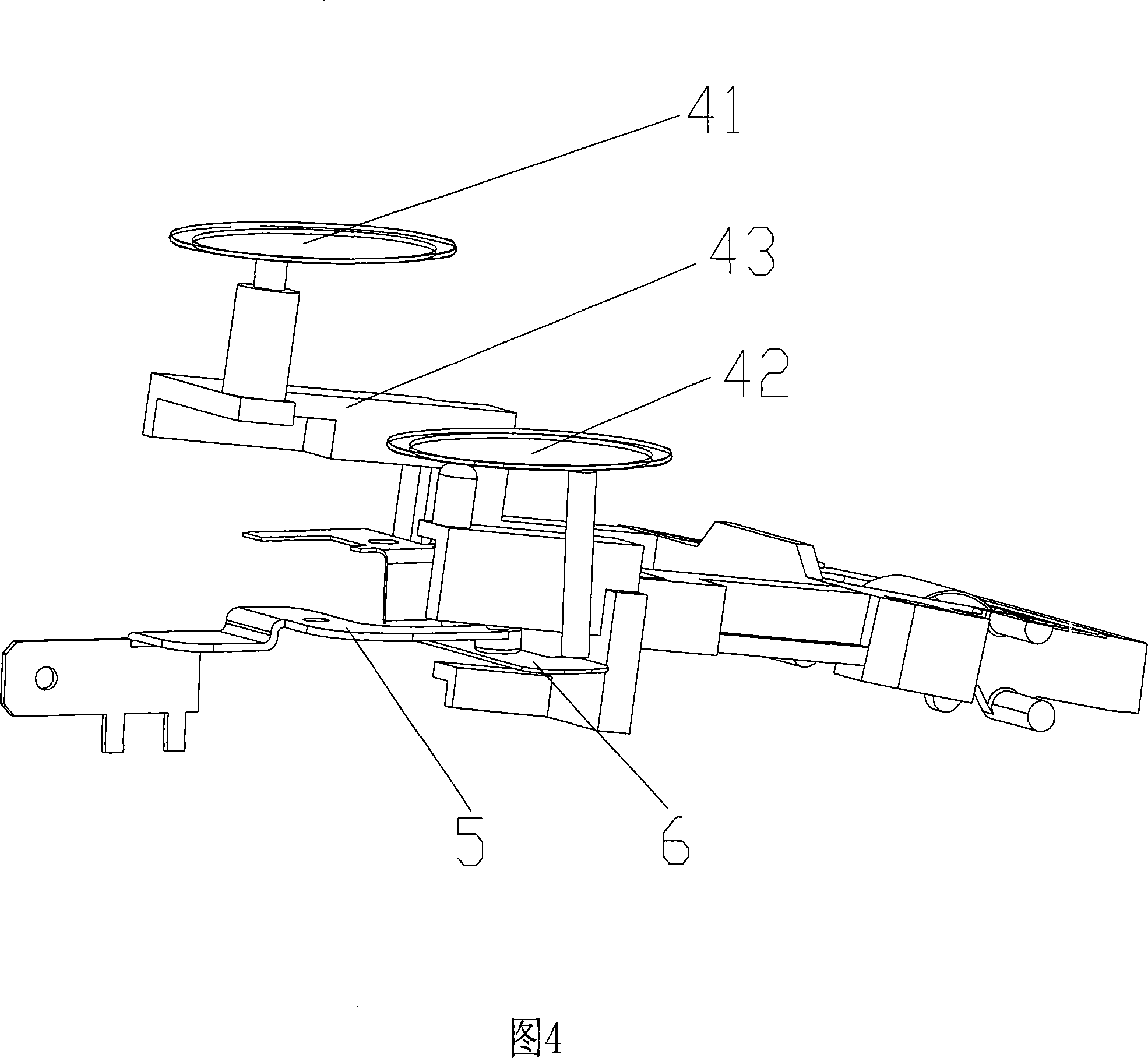
[0025] The liquid heating container of the present invention includes a coffee pot, an electric kettle, a water heater, etc., but is not limited to the above-mentioned heating containers.

[0026] Take electric kettle as example below, the present invention is described in detail. Please refer to Figures 1 to 4, the electric kettle of the present invention includes a container body 1 for holding heated liquid, a heating device 2 for providing heat energy to the container body 1, a connector 3 for transmitting electrical signals, and a connector 3 for connecting The electrical switch contacts of the power supply and the heating device 2, and the thermal control assembly 4 for directly or indirectly controlling the electrical switch contacts, the heating device 2 is located at the lower end of the container main body 1, and is closely attached to the bottom 11 of the container main body 1. The control assembly 4 is in contact with the heating device 2 and is located below the he...


PUM


Abstract

The invention relates to a liquid heating container. The liquid heating container comprises main body of container, heating device, connector for transfering electrical signal, electrical switching contact for connecting the power with the heating device, thermal control module for controlling the electrical switching contact. The heating device is at the lower end of the main body of the container and clings to the bottom of the main body. The thermal control module contacts with the heating device and is under the heating device. A projecting part which projects upwards is set at the bottom of the main body. The thermal control module comprises a touch device for turning on the electrical switching contact and the touch device is installed on the projecting part of the main body. When the liquid in the container is very few, even though the main body inclines, the projecting part firstly appears out from the liquid surface than the other parts of the bottom of the container, because the projecting part is not covered with the liquid, the temperature rapidly accends. After the touch device of the thermal control module in the projecting part takes into action, the electrical switching contact is directly or indirectly turned on, therefore the dry burn of the heating container is effectively prevented.

Description

Technical field: [0001] The invention relates to a liquid heating container, in particular to a liquid heating container such as an electric kettle, a coffee pot and the like provided with a dry-boiling protection structure, which belongs to the transformation technology of the liquid heating container. Background technique: [0002] Liquid heating containers currently on the market, especially electric heating containers such as electric kettles and coffee pots, all have the phenomenon of dry burning when there is no liquid in the container, which directly affects the service life of the electric heating container and easily causes safety accidents. [0003] In response to the above problems, early electric heating containers (such as electric kettles, etc.), such as the electric heating container disclosed in British Patent Publication No. GB9411573, have a bimetallic sheet in contact with the heating device at the bottom of the container. When the container When there is ...

Claims


Application Information

Patent Timeline
IPC IPC(8): A47J27/12A47J36/00H05B1/02
Inventor 林小艺
Owner 佛山市顺德区康迈斯电器有限公司
Why Eureka
Try Eureka